
user manual

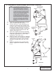
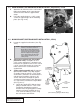


Table Of Contents
- FOREWORD
- TABLE OF CONTENTS
- TOOL AND SUPPLY REQUIREMENTS
- PARTS LIST (Universal Small...
- PARTS LIST (Universal Small...
- PARTS LIST (Universal Small...
- 1. PREPARATION/REMOVAL
- 2. OIL FEED INSTALLATION
- 3. OIL DRAIN INSTALLATION
- 4.1 MAIN BRACKET/SUPERCHARGE...
- 4.2 MAIN BRACKET/SUPERCHARGE...
- 5. CRANK PULLEY AND SUPERCHA...
- 7. FINAL REASSEMBLY AND CHECK
- 6. DISCHARGE DUCTING/CARBURE...
- 7. FINAL REASSEMBLY AND CHECK
P/N: 4GP020-015
©2006 Vortech Engineering, LLC
All Rights Reserved, Intl. Copr. Secured
30MAY06 SmallBlockChev(4GP..015v1.1)
3
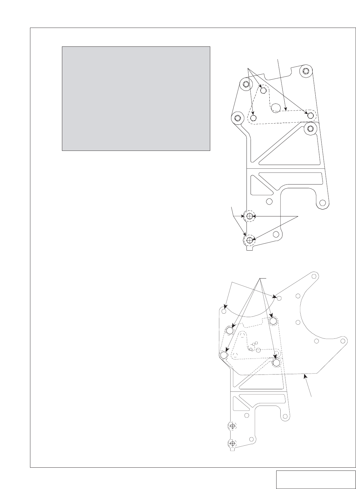
Fig. 4.1-a
NOTE: Some applications (depending on intake
manifold height) may require the reclocking
of the supercharger volute. If reclocking is
required for your application, loosen and
remove the six 1/4-20 cap screws and retain-
ing plates that hold the compressor housing
(volute) to the gearcase. If the compressor
housing does not rotate freely relative to the
gearcase, DO NOT FORCE IT. SERIOUS
SUPERCHARGER DAMAGE MAY OCCUR.
The machined mating surfaces are designed
to prevent pressurized air from escaping and
have minimal tolerances. If the housing will
not move or is very tight, contact Vortech
Engineering immediately at 805 247-0226
and ask our service department for further
assistance.
4.1 MAIN BRACKET/SUPERCHARGER INSTALLATION (Serpentine)
.360" SPACERS
BETWEEN CAST
BRACKET AND
BLOCK
3/8-16 x 4"
HARDWARE
3/8-16 x 5"
HARDWARE
.360" L-SHAPED SPACER
BETWEEN CAST BRACKET
AND CYLINDER HEAD
A. Locate the supplied cast bracket, L-shaped
spacer, and two .360" thick spacers.
B. Use the 3/8-16 x 4" screws and washers to
mount the cast bracket to the cylinder head
using the .360" L-shaped spacer between the
bracket and cylinder head. Use the 3/8-16 x
5" hardware to mount the lower section of the
cast bracket to the block with the two .360"
spacers. (See Fig. 4.1-a.)
C. Locate the supplied supercharger mounting
plate. Secure the plate to the mounting brack-
et with the supplied 3/8-16 x 1.25" screws
and washers. (See Fig. 4.1-b.)
D. Mount the power steering pump (if equipped)
to the back side of the cast bracket using the
supplied 3/8-16 flat-head screws. Reinstall
the power steering pulley. (See Figs. 4.2-b,
4.2-c.)
E. Mount the alternator to the mounting plate
with the supplied 8mm hardware. (See Fig.
4.1-c.)
Fig. 4.1-b
SUPERCHARGER
MOUNTING PLATE
FRONT VIEW
ALTERNATOR
MOUNT
3/8-16 x1.25"
SCREWS AND
WASHERS