FORD SUPE 5.4L/6 R .8L Supe DUTY T Insta rcharge r Sys RUCK llatio tem n Ins tr 50 St 1 ate S 999-2001 mog Lega MODEL Y l per CARBEARS EO #D -21 uctio ns 3-17 ® ENGINEERING, LLC 1650 PACIFIC AVENUE • CHANNEL ISLANDS, CA 93033-9901 • (805) 247-0226 FAX (805) 247-0669 • www.vortechsuperchargers.com • M-F 8:00 AM - 4:30 PM PST P/N: 4FT020-010 ©2002 Vortech Engineering, LLC All Rights Reserved, Intl. Copr. Secured 07FEB02 V2.0(99-01SuperDuty(4FT V2.
FOREWORD Proper installation of this supercharger kit requires general automotive mechanic knowledge and experience. Please browse through each step of this instruction manual prior to beginning the installation to determine if you should refer the job to a professional installer/technician. Please call Vortech Engineering for installers in your area. © 2002 VORTECH ENGINEERING, LLC All rights reserved.
Table Of Contents FOREWORD ..................................................................................................................................... ii TABLE OF CONTENTS .................................................................................................................... iii IMPORTANT NOTES ........................................................................................................................ iv TOOL & SUPPLY REQUIREMENTS ..........................................
Ford 5.4L/6.8L Super Duty IMPORTANT NOTES 1999-2001 Models This kit requires ECM modification and the installation of a Vortech ECM Module. The ECM must be sent directly to Vortech by the installing customer (the charge for this service with module installation has been included in the purchase price). • Included in this kit is a prepaid next-day air shipping box and a credit tag for one (1) Vortech ECM Module.
1999-2001 FORD SUPER DUTY V-10 Installation Instructions 1999-2001 50 State Smog Legal, as per CARB EO #D-213-17 Congratulations on selecting the best performing and best backed automotive supercharger available today... the VORTECH® V-2 ® Supercharger! Before beginning this installation, please read through this entire instruction booklet and the Street Supercharger System Owner's Manual which includes the Automotive Limited Warranties Program and the Warranty Registration form.
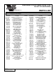
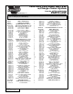
1999-2001 Ford Super Duty 5.4L Part No. 4FT218-010/018SQ ® PARTS LIST ENGINEERING, LLC IMPORTANT: Before beginning installation, verify that all parts are included in the kit. Report any shortages or damaged parts immediately. Part Number Description Quantity Part Number Description 4FT130-026 7U030-026 7P250-034 7P250-082 7P525-067 7P250-066 7U100-055 7P125-026 OIL FEED ASSY.
1999-2001 Ford Super Duty 5.4L Part No. 4FT218-010/018SQ ® PARTS LIST ENGINEERING, LLC IMPORTANT: Before beginning installation, verify that all parts are included in the kit. Report any shortages or damaged parts immediately. Part Number Description Quantity 4FT112-010 4FT012-030 7R002-056 7R002-052 8H040-045 4FT110-010 7P375-106 7P625-016 7U133-024 7A250-075 7F250-021 7J250-001 7S350-200 7U035-001 AIR INLET ASSY DUCT, INLET Ø3.5” S.D.
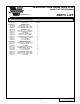
1999-2001 Ford Super Duty 6.8L Part No. 4FT218-020/028SQ ® PARTS LIST ENGINEERING, LLC IMPORTANT: Before beginning installation, verify that all parts are included in the kit. Report any shortages or damaged parts immediately. Part Number Description Quantity 4FT120-020 ECM CHIP PKG/SHIPPING ASSY 1 4FT130-036 7P100-121 7P375-045 7P375-017 7U030-036 7R001-008 OIL DRAIN ASSY.
1999-2001 Ford Super Duty 6.8L Part No. 4FT218-020/028SQ ® PARTS LIST ENGINEERING, LLC IMPORTANT: Before beginning installation, verify that all parts are included in the kit. Report any shortages or damaged parts immediately. Part Number Description Quantity 4FT238-068 4FT145-020 4FD145-010 7U030-046 7P156-082 7U100-055 6Z110-136 FMU ASSY SUPER DUTY FUEL LINE, FEMALE 7" FUEL LINE, MALE 17" 5/32" x 18" VACUUM LINE 5/32" TEE 6" TIE WRAPS 7:1 FMU 1 1 1 1.
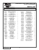
1999-2001 Ford Super Duty 6.8L w/Charge Cooler System ® Part No. 4FT218-030/038SQ PARTS LIST ENGINEERING, LLC IMPORTANT: Before beginning installation, verify that all parts are included in the kit. Report any shortages or damaged parts immediately. Part Number Description Quantity 008110 SMALL SILVER DIE CUT 2 008130 LICENSE PLATE FRAME 1 8N101-110 4FT016-011 4FT016-031 4FT017-010 7C120-065 7C100-040 4FT017-011 WELDED CORE ASSY. V-10 S.D.
1999-2001 Ford Super Duty 6.8L w/Charge Cooler System ® Part No. 4FT218-030/038SQ PARTS LIST ENGINEERING, LLC IMPORTANT: Before beginning installation, verify that all parts are included in the kit. Report any shortages or damaged parts immediately. Part Number Description Quantity 4FT238-068 4FT145-020 4FD145-010 7U030-046 7P156-082 7U100-055 6Z110-136 FMU ASSY S.D.
P/N: 4FT020-010 ©2002 Vortech Engineering, LLC All Rights Reserved, Intl. Copr. Secured 07FEB02 V2.0(99-01SuperDuty(4FT V2.
1. PREPARATION/REMOVAL A. Disconnect the negative battery terminal from the battery. B. The Electronic Control Module (ECM) is the vehicles computer. The ECM should be located above the emergency brake pedal. The wiring harness and plug to the ECM is located on the opposite side of the firewall, in the engine compartment. C. Using a 10mm socket remove the harness and plug from the ECM located below the brake booster in the engine compartment (as the screw is loosened, the connector will slowly release). D.
2. HARMONIC BALANCER AND CRANK PULLEY INSTALLATION NOTE: V-8 ONLY - This process can be done with the fan and fan shroud in place providing your balancer puller is equipped with a 5" or shorter forcing screw. Removing the fan and fan shroud will allow eaiser access to the crank pulley and the front of the engine. A. Drain approximately one gallon of coolant from the radiator (into a clean container for reuse later) using the drain valve located at the bottom of the radiator, driver’s side. B.
2. HARMONIC BALANCER AND CRANK PULLEY INSTALLATION, cont’d. H. Install the harmonic balancer puller. Evenly start the three puller screws (M10 x 1.5). Engage the forcing screw against the pivot and check alignment. NOTE: When using the harmonic balancer puller, pay special attention to alignment of the forcing screw and pivot. Improper alignment can result in crankshaft damage. I.
3. OIL FEED LINE INSTALLATION A. Unplug the connector on the oil pressure sending unit (sending unit should be located on the driver’s side of the block, behind the lower cast radiator inlet) and remove sending unit from engine block. Note a “catch can” may be required if engine oil constantly pours from block. B. Thread the supplied 1/4" NPT fitting into the engine block as shown and tighten. Reinstall the sending unit and connector.
4. OIL DRAIN INSTALLATION, cont’d. E. Check for proper oil drain orientation (position of the oil drain assembly). Install the sealing nut onto the 45° elbow and tighten. F. Reinstall the valve cover and tighten all mounting screws. Replace the sealing gasket if it has been damaged in any way. 5. FUEL PUMP INSTALLATION A. V-10 only - Locate the wiring looms secured to the inner frame rail with plastic snaps on the driver’s side, above the fuel filter.
5. FUEL PUMP INSTALLATION, cont’d. DENOTES FUEL FLOW DIRECTION VORTECH SUPPLIED FUEL PUMP STOCK FUEL FILTER STOCK FUEL LINE FROM TANK V-10 TO FUEL RAILS/ INJECTORS VORTECH SUPPLIED FUEL PUMP STOCK FUEL FILTER STOCK FUEL LINE FROM TANK V-8 Fig. 5-c P/N: 4FT020-010 ©2002 Vortech Engineering, LLC All Rights Reserved, Intl. Copr. Secured 07FEB02 V2.0(99-01SuperDuty(4FT V2.
6. FUEL PUMP RELAY INSTALLATION A. (See Fig. 6-a for the following instructions.) With the two wiring looms above the fuel pump, locate the red wire with black stripe in the wiring loom that runs to the fuel tank. Check the red/ black wire (with a test light) for key-on power, this wire should show power for approximately two to four seconds with the key in the on position. B. From relay terminal #85 tap the yellow wire into the red wire with black stripe using the provided wiretap.
7. IN-TANK FUEL PUMP REPLACEMENT (6.8L H.O. Systems Only), cont’d. I. Remove the three screws securing the fuel pump enclosure’s cover using a 3/16” nut driver and remove the cover. Cut three equally spaced 1/2" long slits in the perimeter of the cover’s fuel pump locating cylinder (see Fig. 7-a). This allows the larger O.D. pump to fit in the cover. Some material may need to be removed from the I.D. of the pump locating cylinder for proper pump fit. J. Remove the stock fuel pump from its enclosure.
8. FUEL MANAGEMENT UNIT (FMU) INSTALLATION, cont’d. E. Secure the fuel lines away from abrasion and exhaust heat with the provided tie wraps. F. Tap into the factory fuel regulator vacuum line with the supplied 5/32" hose and TEE. Route the new hose to the fitting on top of the FMU. Fig. 8-c 9. WATER PUMP AND COOLER INSTALLATION (6.8L H.O. Systems Only) A. Remove the upper shroud, located between the core support and the grille. B. Remove the three screws securing the radiator Fig.
10. MOUNTING BRACKET & SUPERCHARGER INSTALLATION A. Remove the wiring harness bracket and the three mounting screws from the driver’s side front cover of the engine. B. Cut and extend the cam sensor wires using the supplied wire and solderless connectors. Following Fig. 10-a, use a tie wrap to secure the wires to the sensor. C. Loosely screw the 1" wide damper bracket to the driver’s side head using the spacer, M14 screw and washer. Do not tighten. (See Fig. 10-b.) NOTE: There are two threaded holes.
10. MOUNTING BRACKET BRACKET & SUPERCHARGER INSTALLATION, cont’d. J. Thread the 1/8" NPT x #4 x 90° fitting into the oil feed fitting on the supercharger. Rotate the fitting down. Connect the oil feed line to the #4 fitting and tighten. Use only clean engine oil on the oil feed fittings threads. See Appendix A-6 for detail view. NOTE: Do not use any type of sealant on the oil feed fittings.
11. AIR INLET ASSEMBLY, cont’d. E. Connect the cast aluminum duct to the MAF meter using the supplied Ø3.5" x 15" flex hose and secure with #52 hose clamps. F. Install the short end of the Ø5/8" molded elbow hose onto the Ø5/8" bung on the air inlet. NOTE: Refer to Figs. A-4, A-5 and A-7 in the Appendix. G. Cut a 90° section from the stock crank case breather hose and attach to the Ø5/8" molded elbow hose with the Ø5/8" union. Reconnect the other end to the crank case breather on the valve cover.
13. CHARGE COOLER INSTALLATION (6.8L H.O. Systems Only) A. Remove the coolant line attached to the intake manifold (see Fig. 13-a). Remove approximately 2” from the bottom of the coolant line (to allow for clearance of the cooler support bracket) and reinstall. B. Cut 4-1/2” off of the supplied piece of foam tape and the remaining 7-1/2” in half. Thoroughly clean the top portion of the cooler support bracket with alcohol and allow it to dry. Following the diagram (see Fig.
13. CHARGE COOLER INSTALLATION (6.8L H.O. Systems Only), cont’d. Ø 5/8" HOSE UNION CONNECT TO VALVE COVER TO IDLE AIR CONTROL ALUMINUM DUCT DUCT, TUBE C DUCT, TUBE A BYPASS VALVE DUCT, TUBE B CHARGE AIR COOLER FLEX HOSE MAF BRACKET ASSEMBLY Fig. 13-d / See Appendix A-7 for detail 14. HOSE INSTALLATION & SYSTEM FILLING (6.8L H.O. Systems Only) A. Attach the surge tank mounting bracket to the surge tank using the supplied 1/4” hardware. Using Fig.
14. HOSE INSTALLATION & SYSTEM FILLING (6.8L H.O. Systems Only), cont’d. I. Pour 3/4 of a gallon of antifreeze into the surge tank. Fill the system with water until water comes out of the drain fitting, then close the drain valve being careful not to over tighten. J. Continue to fill the system with water until it pours out of the OPEN fitting on the charge cooler. K. Connect the water line from the surge tank to the charge cooler and secure with the provided clamps.
P/N: 4FT020-010 ©2002 Vortech Engineering, LLC All Rights Reserved, Intl. Copr. Secured 07FEB02 V2.0(99-01SuperDuty(4FT V2.
APPENDIX 17 P/N: 4FT020-010 ©2002 Vortech Engineering, LLC All Rights Reserved, Intl. Copr. Secured 07FEB02 V2.0(99-01SuperDuty(4FT V2.
P/N: 4FT020-010 ©2002 Vortech Engineering, LLC All Rights Reserved, Intl. Copr. Secured 07FEB02 V2.0(99-01SuperDuty(4FT V2.0)) 18 FUEL SUPPLY LINE (FROM PUMP) VEHICLE’S RETURN LINE TO TANK FUEL LINE (FEMALE 7”) Fig.
FUEL PRESSURE REGULATOR FUEL SUPPLY LINE (FROM PUMP) 19 V-8 DIAGRAM Fig.A-2 V-8 Diagram FUEL LINE (MALE 7”) FUEL LINE (FEMALE 7”) RETURN LINE (TO TANK) FMU APPENDIX A-2 P/N: 4FT020-010 ©2002 Vortech Engineering, LLC All Rights Reserved, Intl. Copr. Secured 07FEB02 V2.0(99-01SuperDuty(4FT V2.
P/N: 4FT020-010 ©2002 Vortech Engineering, LLC All Rights Reserved, Intl. Copr. Secured 07FEB02 V2.0(99-01SuperDuty(4FT V2.0)) MOUNTING PLATE SPACER, SPRING TENSIONER (NOTE ORIENTATION) Fig.
APPENDIX A-4 V-8 INLET AND DISCHARGE DIAGRAM Standard System CONNECT TO VALVE COVER Ø5/8” UNION TO IDLE AIR CONTROL BYPASS VALVE ALUMINUM INLET DUCT #48 HOSE CLAMP DISCHARGE DUCT FLEX HOSE MAF BRACKET ASSEMBLY (TOP VIEW) Fig. A-4 21 P/N: 4FT020-010 ©2002 Vortech Engineering, LLC All Rights Reserved, Intl. Copr. Secured 07FEB02 V2.0(99-01SuperDuty(4FT V2.
APPENDIX A-5 V-10 INLET AND DISCHARGE DIAGRAM Standard System CONNECT TO VALVE COVER Ø5/8” UNION TO IDLE AIR CONTROL ALUMINUM INLET DUCT ® DISCHARGE DUCT FLEX HOSE BYPASS VALVE BRACKET MAF ASSEMBLY (TOP VIEW) Fig. A-5 P/N: 4FT020-010 ©2002 Vortech Engineering, LLC All Rights Reserved, Intl. Copr. Secured 07FEB02 V2.0(99-01SuperDuty(4FT V2.
APPENDIX A-6 Belt Routing Diagram SUPERCHARGER TENSIONER PULLEY IDLER PULLEY CRANK PULLEY Fig. A-6 23 P/N: 4FT020-010 ©2002 Vortech Engineering, LLC All Rights Reserved, Intl. Copr. Secured 07FEB02 V2.0(99-01SuperDuty(4FT V2.
APPENDIX A-7 V-10 Inlet And Discharge Diagram (H.O. System) CONNECT TO VALVE COVER Ø5/8" HOSE UNION TO IDLE AIR CONTROL ALUMINUM INLET DUCT DUCT, TUBE C DUCT, TUBE A BYPASS VALVE CHARGE AIR COOLER FLEX HOSE DUCT, TUBE B MAF BRACKET ASSEMBLY Fig. A-7 P/N: 4FT020-010 ©2002 Vortech Engineering, LLC All Rights Reserved, Intl. Copr. Secured 07FEB02 V2.0(99-01SuperDuty(4FT V2.
23" CONNECTS TO BOTTOM OF SURGE TANK 8" CHARGE AIR COOLER SURGE TANK SIDE VIEW 25 Ø3.25" x 2" SLEEVE ADAPTER 3/4" NPT BRASS FITTING SURGE TANK TOP VIEW 98" Fig. A-8 FRONT OF VEHICLE WATER COOLER WATER PUMP AIR TO THROTTLE BODY AIR FROM SUPERCHARGER 8" DENOTES FLOW DIRECTION APPENDIX A-8 Water Hose Diagram P/N: 4FT020-010 ©2002 Vortech Engineering, LLC All Rights Reserved, Intl. Copr. Secured 07FEB02 V2.0(99-01SuperDuty(4FT V2.
® ENGINEERING, LLC 1650 PACIFIC AVENUE • CHANNEL ISLANDS, CA 93033-9901 • (805) 247-0226 FAX (805) 247-0669 • www.vortechsuperchargers.com • M-F 8:00 AM - 4:30 PM PST P/N: 4FT020-010 ©2002 Vortech Engineering, LLC All Rights Reserved, Intl. Copr. Secured 07FEB02 V2.0(99-01SuperDuty(4FT V2.