
User manual


45
d) Impedance measurement
Make sure that all circuit parts, circuits and compo-
nents and other objects of measurement are dis-
connected from the voltage and discharged.
Proceed as follows to measure impedance:
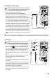
- Switch on the DMM and select measuring range “Ω”.
- Plug the red measuring line into the Ωmeasuringjack(7)and
theblackmeasuringlineintotheCOMmeasuringjack(8).
- Check the measuring lines for continuity by connecting the two
measuring prods. The impedance value must be approximately
0 - 1.5 Ohm (inherent impedance of the measuring lines).
- Now connect the two measuring prods to the object to be
measured.Aslongastheobjecttobemeasuredisnothigh-
impedance or interrupted, the measured value will be indicated
on the display. Wait until the displayed value has stabilised.
With impedances of >1 MOhm, this may take a few seconds.
- If “OL” (overload) appears on the display, you have exceeded
the measuring range or the measuring circuit is interrupted.
- Alwaysremovethemeasuringlinesfromtheobjecttobemeas-
ured after completion of the measurement and switch off the
DMM.
If you carry out an impedance measurement, make sure that the measuring points you touch with the measuring
prodsarefreefromdirt,oil,solderablelacquerorsimilar.Suchcircumstancescanfalsifythemeasuredresult.
e) Diode test
Make sure that all circuit parts, circuits and com-
ponents and other objects of measurement are
disconnected from the voltage and discharged.
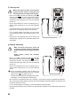
- Switch on the DMM and select the measuring range .
Press the button to switch measurement func-
tions. The diode symbol appears in the display. Pressing this
button again takes you to the first measuring function, etc.
- Plug the red measuring line into the Ωmeasuringjack(7)
and the black measuring line into the COM measuring
jack(8).
- When the measurement input/measurement circuit is open
and short-circuited (e.g., if the diode is defective), “- - - - -”
will be displayed.
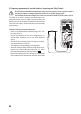
- Connectthetwomeasuringprodswiththeobjecttobemeas-
ured (diode).
- The forward voltage “UF” is shown in volts (V) in the display.
A minus sign in front of the measurement value indicates
that the diode is measured in reverse direction (UR). As a
test, conduct a counter-pole measurement.
- Always remove the measuringlinesfrom the object to be
measured after completion of the measurement and switch
off the DMM.