
Information

Msg[63].bytes&0x34 = 0x32;misplug EEROR ON A INPUT
Msg[63].bytes&0x34 = 0x33;misplug EEROR ON V INPUT
Memory_Overwrite_flag:
Memory Type:
Overwrite
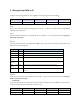
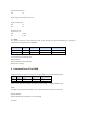
3.3 Comp Data
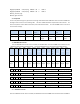
For the Comp Data message, the payload of the message contain MAX,MIN,COMP value of the stored at the DMM The
message format is shown as in the following table. The value of MAX and MIN are represented in ASIC-II format. The
value at Inner/Outer mode is 0x00 at Inner Mode, and is 0x01 at Outer Mode. The value at DMM Function is the same
as the live data message.
Header Length Msg Type DMM
Function
MAX MIN Inner/Outer
Mode
Check Sum
2 Byte 1 Byte 1 Byte 2 Byte 7 Byte 7 Byte 1 Byte 2 Byte
Msg[0]- Msg[1] Msg[2] Msg[3] Msg[4]- Msg[5] Msg[6]-
Msg[12]
Msg[13]-
Msg[19]
Msg[20] Msg[21]-
Msg[22]
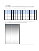
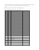
3.4
NOCOMP Data Transfer
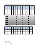
Once the NOCOMP data transfer mode is enabled, the NOCOMP data stored at the DMM will be transfer from the
DMM to PC at the following message format. The value at DMM Function is the same as the live data message.
Header Length Msg
Type
DMM
Functio
n
Display
1
Display2 Display
3
Display
4
Display
5
Second
freque
ncy
Unit
Display
6
Status
Check
Sum
2 Byte 1 Byte 1 Byte 2 Byte 7 Byte 8 Byte 10 Byte 8 Byte 8 Byte 3 Byte 4 Byte 5 Byte 2 Byte
Msg[0]-
Msg[1]
Msg[2] Msg[3] Msg[4]-
Msg[5]
Msg[6]-
Msg[12]
Msg[13]
-Msg[20
]
Msg[21]
-Msg[30
]
Msg[31]
-Msg[38
]
Msg[39]
-Msg[46
]
Msg[47
]-Msg[4
9]
Msg[50]
-Msg[53
]
Msg[54]
-Msg[58
]
Msg[59]
-Msg[60
]
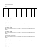
Msg[54]: Not required
0 0 1 1 Sign2_flag Sign1_flag comp_min_pol_flag comp_max_pol_flag
Msg[55]:
::
:Required
0 0 1 1 Max_flag Min_flag Avg_flag Rel_flag
Msg[56] :
::
:Not required
0 0 1 1 Ol2_flag Ol1_flag Manu_flag Hold_flag
Msg[57]:
::
:Hv_Warning_flag Required
0 0 1 1 log_VOID_flag
Loz_flag Hv_Warning_flag Auto_power_flag
Msg[58]:
::
:Not required
0 0 1 1 log_H_flag Comp_flag Pass_flag Inner_flag
3.5
COMP Data Transfer
Once the COMP data transfer mode is enabled, the COMP data stored at the DMM will be transferred from the DMM to