
Information
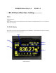
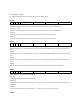
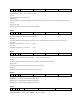

3.2 Live Data
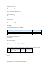
For the Live Data message, the payload of the message contain the corresponding values with the current measurement
mode of the DMM, where it can be separated into DMM Function, Display 1, Display 2, Display 3, Display
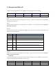
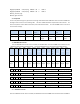
4,Display5,Display6and Status. The message format is shown as in the following table.
Header Length Msg
Type
DMM
Functio
n
Display
1
Display2 Display
3
Display
4
Display
5
Second
freque
ncy
Unit
Display
6
Display
Bar
Status
Check
Sum
2 Byte 1 Byte 1 Byte 2 Byte 7 Byte 8 Byte 10 Byte 8 Byte 8 Byte 3 Byte 4 Byte 2 7 Byte 2 Byte
Msg[0]-
Msg[1]
Msg[2] Msg[3] Msg[4]-
Msg[5]
Msg[6]-
Msg[12]
Msg[13]
-Msg[20
]
Msg[21]
-Msg[30
]
Msg[31]
-Msg[38
]
Msg[39]
-Msg[46
]
Msg[47
]-Msg[4
9]
Msg[50]
-Msg[53
]
Msg[54]
-Msg[55
]
Msg[56]
-Msg[63
]
Msg[64]
-Msg[65
]
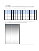
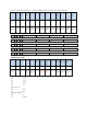
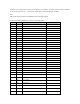
DMM Function: Msg[4] – Msg[5]
Two byte is used to represent the selected measurement mode (Msg[4]) and the measurement range (Msg[5]) of the
DMM. All the available measurement mode of the VC890 DMM is listed at the following:
Msg[4]:
Value (HEX) Measurement Mode
0x00 ACV
0x01 Low-Pass Filter
0x02 DCV
0x03 ACV+DCV
0x04 DCmV
0x05 Frequency
0x06 Duty Cycle
0x07 Resistance
0x08 Short-Circuit Test
0x09 Diode
0x0A Capacitance
0x0B Celsius
0x0C Fahrenheit
0x0D DCuA
0x0E ACuA
0x0F DCmA
0x10 ACmA
0x11 DCA
0x12 ACA
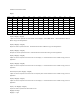
The DMM range can be decode at the HEX value at Msg[5], this single byte vale represents the select range of operation