
Information
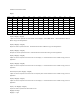
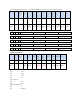
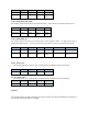

Header Length Command High Value Check Sum
2 Byte 1 Byte 1 Byte 7 Byte 2 Byte
Msg[0]- Msg[1] Msg[2] Msg[3] Msg[4]-
Msg[10]
Msg[11]-
Msg[12]
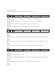
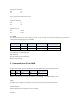
4.2 SET_COMP_MODE_LOW_VALUE
This message contains the low value of the comparison mode. The low value is represented in ASIC-II format.
Header Length Command Low Value Check Sum
2 Byte 1 Byte 1 Byte 7 Byte 2 Byte
Msg[0]- Msg[1] Msg[2] Msg[3] Msg[4]-
Msg[10]
Msg[11]-
Msg[12]
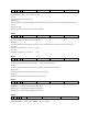
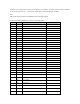
4.3 SET_COMP_MODE_ALL
This message contains the high, low, inner/outer value of the comparison mode. The high and low value is
represented in ASIC-II format.
The value at Inner/Outer mode is 0x00 at Inner Mode, and is 0x01 at Outer Mode.
Header Length Command High Value Low Value Inner/Outer Mode Check Sum
2 Byte 1 Byte 1 Byte 7 Byte 7 Byte 1 Byte 2 Byte
Msg[0]- Msg[1] Msg[2] Msg[3] Msg[4]-
Msg[10]
Msg[11]-
Msg[17]
Msg[18] Msg[19]-
Msg[20]
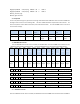
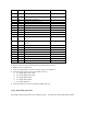
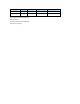
4.4 SET _System_Time
This message sends “Check_System_Time” Command from PC to VC890 to check its internal timer
Header Length Command System timer Check Sum
2 Byte 1 Byte 1 Byte 6 Byte 2 Byte
4.5 SET _System_Date
This message sends “Check_System_Date” Command from PC to VC890 to check its internal Date
Header Length Command System Date Check Sum
2 Byte 1 Byte 1 Byte 6 Byte 2 Byte
4.6 Result
This message indicates the data transmission result of the message that required handshaking for guarantee of
successful data exchange between PC and DMM.