
User manual


- Turn the DMM on and select measuring range “hFE”.
- Disconnect all measuring leads from the measuring instrument.
- Attach the optionally available measuring adapter to the three measuring
sockets COM (5) + V (8) + mA (7).
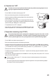
- Insert the transistor to be tested into the corresponding header observing
the correct polarity. The left header is intended for NPN types and the right
header for PNP types. SMD types can also be tested.
- The amplication factor “hFE” is displayed.
- After measuring, remove the adapter and turn the DMM off. Turn the rotary
switch to the position “OFF” or turn the device off via the “POWER” switch.
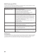
- Turn the DMM on and select measuring range “°C”.
- Disconnect all measuring leads from the measuring instrument.
- Connect the thermal sensor provided and/or the optional measurement adapter to the DMM. Make sure that the
connection is correct (i.e. the poles are the right way around). Turn the plug so that the sensor port marked “COM”
(-) is connected to the “COM” (5) socket and the sensor port marked “°C“(+) is attached to the “°C” (7) socket.
- Now expose the sensor tip to the temperatures.
- The display shows the temperature on the sensor. If “I” appears, the measuring range was exceeded or there is
no sensor connected.
- After measuring, remove the adapter and turn the DMM off. Turn the rotary switch to the position “OFF” or turn the
device off via the “POWER” switch.
If the two sockets “COM” (5) and “°C” (7) are short-circuited, the ambient temperature of the measuring
device is displayed.
The use of K-type sensors with miniature plugs requires the application of the optional measuring adapter
(see chapter “Optional measuring adapter”).