
Instructions


32
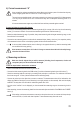
d) Diode test
Make sure that all objects that you wish to measure (including circuit components, circuits and
component parts) are disconnected and discharged.
- Switch on the DMM and select the measuring function.
- ConnecttheblackmeasuringleadtotheCOMsocket(5)andtheredmeasuringleadtothemA/Ωsocket(7).
- Check the measuring leads for continuity by connecting both probe tips to one another. The value must be approx.
0 V. The open-circuit voltage is approx. 3 V.
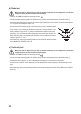
- Now connect the two measuring tips to the object that you want to measure (diode).
- Ifthe“overow”iconisdisplayed,thediodeismeasuredinreversedirectionorthe
diode is defective (open circuit). Try taking the measurement again with the oppo-
site polarity. The red measuring lead corresponds to the positive pole (anode), the
black measuring lead to the negative pole (cathode). A silicon diode has a forward
voltage of approx. 0.5 - 0.8 V.
- After measuring, remove the measuring leads from the measured object and switch
offtheDMMatthe“POWER”button(3).
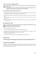
e) Continuity test
Make sure that all objects that you wish to measure (including circuit components, circuits and
component parts) are disconnected and discharged.
- Switch on the DMM and select the measuring function
- ConnecttheblackmeasuringleadtotheCOMsocket(5)andtheredmeasuringleadtothemA/Ωsocket(7).
- A measured value of approx. <10 ohm is detected as continuity and a continuous tone is emitted.
- Assoonasthe“overow”iconisdisplayed,youhaveexceededthemeasuringrangeorthemeasuringcircuitis
open.
- Aftermeasuring,removethemeasuringleadsfromthemeasuredobjectandswitchofftheDMMatthe“POWER”
button (3).