
User manual


60
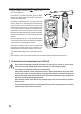
- After taking a measurement, remove the leads from the measured object and switch the DMM off.
When taking a resistance measurement, ensure that the points that come into contact with the measuring
probes are free from dirt, oil, solder and other impurities. These substances may distort the measurement.
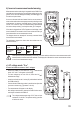
The “REL” button only works when a measurement is displayed. It cannot be used when “OL” is displayed.
l) Diode test
Ensure that all objects that you want to measure (including circuit components, circuits and com-
ponent parts) are disconnected and discharged.
- Switch the DMM on and select the mode.
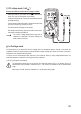
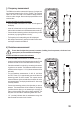
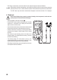
- Press “SELECT” twice to switch to diode test mode. The diode
symbol and “V” will appear on the display. Press the button
again to switch to the next mode.
- InserttheredtestleadintotheΩmeasurementsocket(G)and
the black test lead into the COM measurement socket (H).
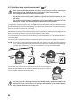
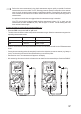
- Check the test leads for continuity by connecting both measur-
ing probes to one another. A value of approx. 0.000 V should
be shown.
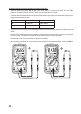
- Now connect the two measuring probes to the object to be
measured (diode). The red test lead to the anode (+), the black
test lead to the cathode (-).
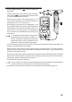
- The continuity voltage “UF” will be shown in volts (V). “OL”
indicates that the diode is reverse-biased or defective. Try tak-
ing the measurement again with the opposite polarity.
- After taking a measurement, remove the leads from the meas-
ured object and switch the DMM off.