
User manual

45
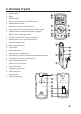
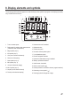
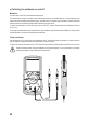
6. Overview of parts
A Rubber protector
B Display
C REL/HOLD button
D Rotary control for selecting the measurement mode
E mAµA measurement socket
F Measurement socket for clamp transformer (+)
G VΩmeasurementsocket(“positivepotential”fordirectvoltages)
H COM measurement socket (reference potential, “negative”)
I SELECT button for selecting the mode
J LowImp.400kΩbuttonforchangingtheimpedance
K Base with sliding cover for optional fastening strap
L Connection thread for stand
M Battery compartment screw
N Fold-out stand
O Battery compartment
P Battery and fuse compartment cover
Q Self-resetting PTC protection elements for mA/µA measurement input
R PTC protection element for current clamp input
S Battery compartment on the rear
T Adjuster for DC zero calibration
U Current clamp sensor
V Tangible grip range marking
W Clamp opening lever
S Operating switch
Y Safety connection plug