
User manual

58
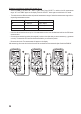
h) Resistance measurement
Ensure that all objects that you want to measure (including circuit components, circuits and com-
ponent parts) are disconnected and discharged.
Proceed as follows to measure the resistance:
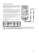
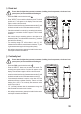
- SwitchtheDMMonandselectthe“Ω”measurementmode.
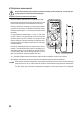
- InserttheredtestleadintotheΩmeasurementsocket(G)and
the black test lead into the COM measurement socket (H).
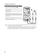
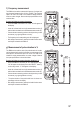
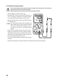
- Check the test leads for continuity by connecting both measur-
ing probes to one another. The multimeter should then show a
resistancevalueofapprox0-0.5Ω(inherentresistanceofthe
test leads).
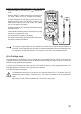
- For low-impedance measurements of <600 Ω, hold down
the “REL” button (C) for approximately one second when the
measuring probes are short circuited. This ensures that the
inherent resistance of the test leads does not affect the resist-
ancemeasurement.Thedisplayshouldshow0Ω.Autorange
is thereby disabled.
- Connect the measuring probes to the object that you want to
measure. The measurement will be shown on the display (pro-
vided that the object you are measuring is not highly resistive
or disconnected). Wait until the display stabilises. This may
takeafewsecondsforresistancesgreaterthan1MΩ.
- “OL” (overload) indicates that the measurement range has been exceeded or that the circuit is broken.
- After taking a measurement, remove the leads from the measured object and switch the DMM off.
When taking a resistance measurement, ensure that the points that come into contact with the measuring
probes are free from dirt, oil, solder and other impurities. These substances may distort the measurement.
The “REL” button only works when a measurement is displayed. It cannot be used when “OL” is displayed.