
User manual


46
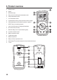
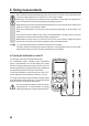
6. Product overview
A Rubber protector
B Display
C REL/HOLD button
D Rotary control for selecting the measurement mode
E mA/µA measurement socket
F 10 A measurement socket
G
VΩmeasurementsocket(“positivepotential”fordirectvoltages)
H COM measurement socket (reference potential, “negative”)
I SELECT button for selecting the mode
J Lowimp.400kΩbuttonforchangingtheimpedance
K NCV sensor area (front side)
L Base with sliding cover for optional fastening strap
M Connection thread for stand
N Battery compartment screw
O Folding stand bracket
P Battery compartment
Q Battery and fuse compartment cover
R Self-resetting PTC protection elements for mA/µA measurement input
S F1 fuse: