
User manual

54
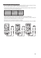
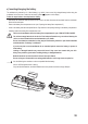
k) Diode test
Make sure that all objects that you wish to measure (including circuit components, circuits and
component parts) are disconnected and discharged.
- Switch on the DMM and select the desired mode .
- Press “SELECT” twice to switch to diode test mode. The diode
symbol and “V” will appear on the display. Press the button again
to switch to the next measuring mode.
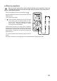
- PlugtheredleadintotheΩterminal(G)andtheblackleadintothe
COM terminal (H).
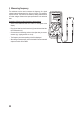
- Check the measuring leads for continuity by connecting both
measuring probes to one another. A value of approx. 0.000 V
should be shown.
- Connect the two measuring probes to the object that you want to
measure (diode). Connect the red lead to the anode (+) and the
black lead to the cathode (-).
- The continuity voltage (“UF”) will be shown in Volts (V). “OL” indi-
cates that the diode is reverse-biased or defective. Try taking the
measurement again in the opposite polarity.
- After taking a measurement, remove the leads from the measured object and switch off the DMM.
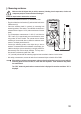
l) Continuity test
Make sure that all objects that you wish to measure (including circuit components, circuits and
component parts) are disconnected and discharged.
- Switch on the DMM and select the desired mode .
- Press the “SELECT” button once to switch to continuity test mode.
ThecontinuitytestsymbolandtheΩsymbolwillappearonthe
display. Press the button again to switch to the next measuring
mode.
- PlugtheredleadintotheΩterminal(G)andtheblackleadintothe
COM terminal (H).
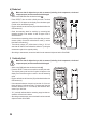
- Ifthemeasuredresistanceisequaltoorlessthan10Ω,themul-
timeter will beep to indicate continuity. The beeps stop when the
resistanceexceeds100Ω.Thecontinuitytestmeasuresresist-
ances of up to 400 Ohm.
- “OL” (overload) indicates that the measuring range has been ex-
ceeded or that the circuit is broken.
- After taking a measurement, remove the leads from the measured
object and switch off the DMM.