
User manual

41
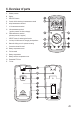
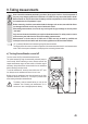
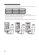
6. Overview of parts
A Rubber protector
B Display
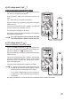
C REL/HOLD button
D Control dial for selecting the measurement mode
E mAµA measurement terminal
F 10 A measurement terminal
G VΩmeasurementterminal
(“positive potential” for direct voltages)
H
COM measurement terminal
(reference potential, “negative”)
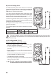
I SELECT button for selecting the function
J LowImp.400kΩbuttonforchangingtheimpedance
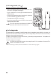
K Base with sliding cover for optional mounting
L Connection thread for stand
M Battery compartment screw
N Fold-out stand
O Battery compartment
P Battery and fuse compartment cover
Q Resettable PTC fuse
R F1 fuse