
User manual


59
c) Direct current ( )
• Select < > mode. [ DC µ A ] will appear on the display.
• The main display indicates the measured current.
- A minus symbol [ –]indicatesthatthecurrentisowingintheoppositedirection(orthatthemeasuringleadsare
connected in the wrong polarity).
d) Alternating current ( )
• Select < > mode. [ AC µ A ] will appear on the display.
• The main display indicates the measured current.
• The small display indicates the measured frequency.
• The symbol indicates a True RMS value.
18. Measuring – Frequency (electronic)
The multimeter can be used to measure signal voltage frequencies from 10 Hz to 40 MHz. The maximum input is
30 Vrms.
• This mode is not suitable for taking measurements on mains voltages.
- For mains voltages, the frequency is measured and displayed along the
voltage. Refer to the corresponding chapters.
• Observetheinputspecicationsinthetechnicaldata.
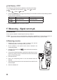
1. Select < Hz% > mode. [ Hz % ] will appear on the display.
2. Insert the red test lead into the socket and the black test lead into
the COM socket.
3. Connect the two measuring probes in parallel to the object that you want to
measure (e.g. signal generator or circuit).
4. The main display indicates the measured frequency. The small display
indicates the duty cycle in %.
5. After measuring, remove the test leads from the measured object and turn
the multimeter off.