
Instructions

52
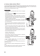
m) 3-phase rotation indicator (“Motor”)
You can use the multimeter to identify the direction of rotation in a 3-phase power supply. Only two test leads are nee-
ded in this mode. The phase conductors (L1, L2 and L3) must be scanned one after another. The multimeter detects
thephaseshiftandindicatesthedirectionofrotation(rotaryeld)withanarrow.
This mode can only be selected in the AC-V range.
Proceed as follows:
- Turn the multimeter on and select “Motor” mode. “AC” and “V” will appear
on the display.
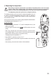
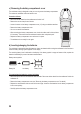
- Insert the red test lead into the socket (11) and the black test lead
into the COM socket (10).
- Press and hold the “SELECT” button for two seconds. You will hear a
beepandthelocksymbolwillstarttoash.Automaticrangeselectionwill
be disabled and the 600 V range will be selected. A reading of approxi-
mately 0.0 V will appear on the display.
- Connect the black test probe to the L1 phase conductor. This connection
should be kept in place for the entire test. Connect the red test probe to
the L2 phase conductor.
- When two phase conductors are detected, the multimeter will beep and
displaytheratedvoltage.Thelocksymbolwillstopashingandstaycon-
stant.
- Connect the red test probe to phase conductor L3 within 5 seconds. If the
probe is not connected within 5 seconds, the multimeter will stop taking
measurements and you will need to start again.
- The multimeter analyses the phase shift of the three phase conductors
and indicates the direction of rotation using two symbols. The direction of
the arrow shows the direction of rotation:
Clockwise = Right-pointing arrow
Anticlockwise = Left-pointing arrow
- Press the “SELECT” button to take another measurement. To disable this
mode, press and hold “SELECT” for 2 seconds.
- After measuring, remove the test leads from the measured object and turn
the multimeter off.
The “RANGE”, “MAX MIN”, “REL”, “Hz” and “HOLD” buttons are
automatically disabled in this mode.
There may be signal interference when measuring 3-phase motors with a
variable frequency drive.
To minimize interference, extend the measuring duration to at least 30 se-
conds.
The rated voltage may not be entirely accurate for motors with a variable
frequency drive and should be used for reference purposes only.