
Instructions


50
j) Measuring capacitance
Make sure that all objects to be measured (including circuit
components, circuits and component parts) are disconnected
and discharged.
Always pay attention to the polarity when using electrolytic
capacitors.
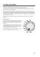
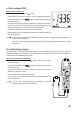
- Turn the multimeter on and select mode.
- Insert the red test lead into the
socket (11) and the black test lead
into the COM socket (10).
Due to the sensitive measuring input, the display may show a rea-
ding even with “open” measuring leads. Press the “REL” button to
reset the display to “0”. Automatic range selection will be disabled.
This is recommended for small capacitances in the nF range.
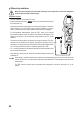
- Connect the two test probes (red = positive / black = negative) to the object
that you want to measure (capacitor). The capacitance will be shown on the
display after a few seconds. Wait until the display stabilises. This may take
a few seconds for capacitances greater than 40 µF.
- “OL” (overload) indicates that the measuring range has been exceeded.
- After measuring, remove the measuring leads from the measured object
and turn the multimeter off.
k) Measuring frequency (electronic)
The multimeter can be used to measure signal voltage frequencies from 10
to 40 MHz. The maximum input is 30 Vrms. This mode is not suitable for ta-
kingmeasurementsonmainsvoltages.Observetheinputspecicationsinthe
technical data.
For mains voltages, use the “Hz” function in voltage or current mode.
Proceed as follows:
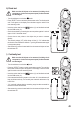
- Turn the multimeter on and select “Hz” mode. “Hz” will appear on the display.
- Insert the red test lead into the socket (11) and the black test lead
into the COM socket (10).
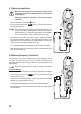
- Connect the two measuring probes in parallel to the object that you want to
measure (e.g. signal generator or circuit).
- The frequency will be displayed together with the corresponding unit..
- After measuring, remove the test leads from the measured object and turn
the multimeter off.