
Instructions


49
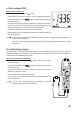
h) Diode test
Make sure that all objects to be measured (including circuit
components, circuits and component parts) are disconnected
and discharged.
- Turn the multimeter on and select mode.
- Press “SELECT” twice to switch the measurement mode. The diode symbol
and “V” will appear on the display. Press the button again to switch to the
next measuring mode.
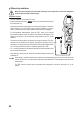
- Insert the red test lead into the socket (11) and the black test lead
into the COM socket (10).
- Check the test leads by connecting the two test probes together. A value of
approx. 0.000 V should be shown.
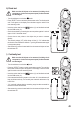
- Connect the two test probes to the object that you want to measure
(diodes).
- The continuity voltage (“UF”) will be shown in Volts (V). “OL” indicates that
the diode is reverse-biased or defective. Try taking the measurement again
in the opposite polarity.
- After measuring, remove the test leads from the measured object and turn
the multimeter off.
i) Continuity test
Make sure that all objects to be measured (including circuit
components, circuits and component parts) are disconnected
and discharged.
- Turn the multimeter on and select mode.
- Press the “SELECT” button to switch measurement modes. The continuity
testsymbolandtheΩsymbolwillappearonthedisplay.Pressthebutton
again to switch to the next measuring mode.
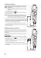
- Insert the red test lead into the socket (11) and the black test lead
into the COM socket (10).
- Ifthemeasuredresistanceisequaltoorlessthan10Ω,themultimeterwill
beep to indicate continuity. The continuity test measures resistances of up
to 600 Ohm.
- “OL” (overload) indicates that the measuring range has been exceeded or
that the circuit was disconnected.
- After measuring, remove the test leads from the measured object and turn
the multimeter off.