
Instructions


48
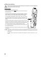
g) Measuring resistance
Make sure that all objects to be measured (including circuit components, circuits and component
parts) are disconnected and discharged.
Proceed as follows:
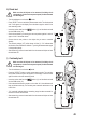
- Turnthemultimeteronandselect“Ω”mode.
- Insert the red test lead into the socket (11) and the black test lead into
the COM socket (10).
- Check the test leads by connecting the two test probes together. A resistance
value of approx 0–0.5 Ω should be shown (inherent resistance of the test
leads). The lead resistance in high-impedance measurements is negligible.
- For low-impedance measurements, press the “REL” button (9) to discount
the inherent impedance of the test leads in the resistance measurement. The
displaywillberesetto0Ωandautomaticrangeselection(“AUTO”)willbe
disabled.
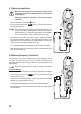
- Connect the two test probes to the object that you want to measure. The mea-
surement will be indicated on the display (provided that the object you are
measuring is not highly resistive or disconnected). Wait until the display stabili-
ses.Thismaytakeafewsecondsforresistancesgreaterthan1MΩ.
- “OL” (overload) indicates that the measuring range has been exceeded or that
the circuit was disconnected.
- After measuring, remove the test leads from the measured object and turn the
multimeter off.
When taking a resistance measurement, make sure that the measuring points you touch with the probe
tips are free from dirt, oil, solder lacquer and other similar substances. These substances may distort the
measurement.
The “REL” button only works when a measured value is displayed. It cannot be used when “OL” is dis-
played.