
Instructions

40
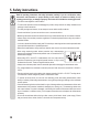
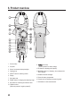
6. Product overview
1 Current clamp
2 Grip area
3 Sensor for automatic display backlight
4 Opening lever
5 SELECT button for switching modes
6 Display
7 Soft rubber seal
8 RANGE button for changing the measuring range
9 REL button for measuring the reference value
10 COM test socket
(Reference potential, “negative potential”)
11 test socket
(“Positive potential” for direct voltage)
12 Hz button for displaying the frequency
13 MAX/MIN button for displaying the maximum/mini-
mum readings
14 Disables automatic backlight
15 Screw for battery compartment
16 Control knob for selecting the measuring mode
17 Hold button to retain measurements