
User manual

54
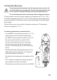
h) Diode Test
Make sure that all circuit parts, circuits and components and other objects of
measurement are disconnected from the voltage and discharged.
-
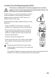
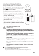
Turn the DMM on and select measuring
function
. Press “MODE” button 1 x to switch
measurement functions. The symbol for diode test now
appears in the display. Pressing this button again takes you
to the next measuring function, etc.
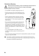
- Plug the red measuring line into the V measuring jack (9)
and the black measuring line into the COM measuring jack
(8).
- Check the measuring lines for continuity by connecting the
two measuring prods. The value must be approximately
0.000 V.
- Connect the two measuring prods with the object to be
measured (diode).
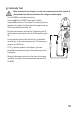
- The display shows the continuity voltage “UF” in volt (V). If
“OL” appears, the diode is measured in reverse direction
(UR) or the diode is faulty (interruption). Perform a coun-
ter-pole measurement to check.
- Remove the measuring lines from the object to be meas-
ured after completion of the measurement and switch off
the DMM.