
Instructions

45
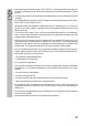
23 Symbol for low impedance
24 Symbol for direct current ( )
25 Polarityindicationforcurrentowdirection(minuspole)
26 Symbol for alternating current ( )
27 Measured value is AC+DC-coupled
28 Warning symbol for dangerous voltage or additional warning symbol when the measured value is exceeded
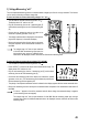
REL Button for relative value measuring (= reference value measuring)
SELECT Button for switching the subfunctions
RANGE Button for manual measurement range selection
MAX MIN Button for maximum and minimum value storage
HOLD Button for manually capturing the currently measured value.
PEAK Peak value storage (250 µs impulse recording)
OL Overload = the measurement range was exceeded
OFF Switchposition“Meteroff”
Symbol for the diode test
Symbol for the acoustic continuity tester
Symbol for the capacity measuring range
Symbol for alternating current
Symbol for direct current
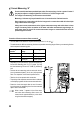
COM Measuring connection reference potential
mV Measuring function voltage measuring, Millivolt (exp.-3)
V Measuring function voltage measuring, Volt (unit of electric voltage)
A Measuring function current measuring, Ampere (unit of electric current)
mA Measuring function current measuring, Milliampere (exp.-3)
µA Measuring function current measuring, Microampere (exp.-6)
Hz% Measuring function frequency, Hertz (unit of frequency) and pulse duration ratio in %
Ω Measuringfunctionresistance,Ohm(unitofelectricalresistance)
Motor Measuring function 3-phase rotating direction display
LPF Low-passlterfunctiontolterhigh-frequencyfaultsatAC-Vmeasurement
AC+DC Alternate and direct current coupled measuring function
Button to switch off the automatic lighting for the display
Button for the LED lamp
Symbol for the fuses used