
Instructions

40
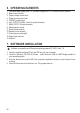
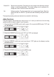
6. OPERATING ELEMENTS
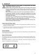
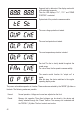
1. LED panel meter display with C.V. (Constant voltage) and C.C (Constant current) indicator
2. Rear control indicator
3. Output voltage control knob
4. Output current control knob
5. POWER (on/off) switch
6. AUX. OUTPUT 5A MAX. (Auxiliary output terminals)
7. MAIN OUTPUT (Output terminals)
8. Mode selection switch
9. Recall selection switch
10. Remote control terminal
11. Cooling fan air intake grille
12. Power input and fuse
13. USB port
7. SOFTWARE INSTALLATION
Software is compatible with Windows
®
operating systems XP, 2003, Vista, 7 ,8
1. Insert the supplied software CD into the DVD drive of your computer.
2. Located in directory USB CP210x Drivers... install the driver (USB to UART Bridge) suitable to
your operating system.
3. Copy the directory hcs from the CD to the computer’s application directory or any location of your
choosing.
4. Open the le hcs.exe in the directory hcs. The progam starts up.