
Instructions


TECHNICAL DATA
Indication range .............................................999999.99 kWh
Mains connection ...........................................Three-phase four-wire network, direct measuring
Power rating ..................................................3 x 230/400 V/AC
Voltage range ................................................3 x 161 - 300/279 - 520 V/AC
Network frequency .........................................50/60 Hz
Reference current (lb)/phase .........................10 A
Limit current/phase ........................................100 A
Start-up current/phase ...................................0.04 A
Accuracy rating ..............................................1 (IEC 62053-21)
Accuracy (symmetrical) .................................>0.5 A: ±1.5% (CosPhi 1)
.......................................................................>1 A - 100 A: ±1.0% (CosPhi 1)
.......................................................................>1 A: ±1.5% (CosPhi 0.5 inductive)
.......................................................................>2 A - 100 A: ±1,0% (CosPhi 0.5 inductive)
>1 A: ±1.5% (CosPhi 0.8 capacitive)
.......................................................................>2 A - 100 A: ±1.0% (CosPhi 0.8 capacitive)
Accuracy (asymmetrical) ...............................>1 A - 100 A: ±2.0% (CosPhi 1)
.......................................................................>2 A - 100 A: ±2.0% (CosPhi 0.5 inductive)
Own power consumption ...............................2 W/10 VA per phase
Clamping capacity .........................................0.8 - 50 mm²
Terminal tightening torque .............................1.2 Nm
Pulse constant, visually ................................1000 pulse/kWh
Fastening .......................................................35 mm DIN rail, independent of position
Dielectric withstanding voltage ......................2 kV (max. 1 minute), 6 kV (max.1.2 µs pulse)
Dielectric withstanding current .......................3000 A (max. 0.01 s)
Front panel material .......................................PC (polycarbonate)
Housing material ............................................ABS
Dimensions (H x W x D) ................................110 x 70 x 64.5 mm
Mounting width ..............................................4 modules (TE)
Weight ...........................................................approx. 340 g
Operating conditions ......................................-10 °C to +50 °C, ≤75%rF (not condensing)
Storage conditions .........................................-30 °C to +70 °C, ≤95%rF (not condensing)
Protection category ........................................IP54 (front)
Protection class .............................................2
Active energy meter norm .............................IEC 62053-21
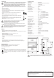
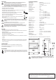
Extended dimensions are shown in the following sketch in millimetres:
The cross section of the power cable and corresponding cable inlet fuse must be
adjusted to the specic installation. It is the responsibility of the installer/system planner.
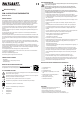
CONNECTION
In order to ensure correct icommissioning, you should read these operating instructions
including the safety instructions thoroughly and attentively before using the device!
You may only connect the unit when the voltage is off. For the installation, observe the
basic principles of electrical engineering: Cut off power supply, secure against being
switched on again, short-circuit, check for presence of voltage.
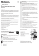
• Connection of the energy meter is carried out for every external conductor by means of series connec-
tion.
• Inputs are on the top side (1).
• Outputs are on the bottom side (3).
• Connect the unit at both screw terminals as shown in “Individual part description”. Arrow markers
correspond to current direction).
• Insulation on the connection cables at the contact points must be stripped for min.
12 mm.
• Always use appropriate crimp ferrules with multi-core conductors.
• Loosen the screw terminals with a Phillips-screwdriver (size PZ2) or a slotted screw-
driver (size 1.2 x 6.5 mm).
• Insert individual conductors into corresponding terminals and tighten them with the
torque of 1.2 Nm.
• Ensure correct t of the conductors in the terminals.
Use of proper screwdriver and correct torque during installation is essential, since
inadequate fastening leads to overheating and may cause re.
• Replace the terminal covers on the unit and screw them down carefully.
A seal can be put through the fastening screw (7) when terminal cover is closed. Thus, the
connections can be protected against tampering.
The energy meter is only capable of cumulative energy consumption metring. Therefore,
the reverse current will still be detected as forward current (rewind lock). Please be
aware of this when using the meter.
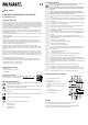
DISPLAY
• The energy consumption is indicated on the main display in kWh.
• Each individual external conductor is additionally furnished with a colour LED display (6) for symmetrical
load control.
• Relevant LED ashes with different frequency depending on the load.
Small load = slow ashing
Large load = from fast ashing to constant light
• Displays for L1, L2 and L3 have different colours for better distinction between them.
L1 = yellow
L2 = green
L3 = red
• The red light-emitting diode (5) can be used as a metrological constant for all three phases.
It ashes with the frequency of 1000 pulses/kWh and can be used for further data processing with
optional measuring accessories.
GETTING STARTED
After successful wiring check, put the energy meter into operation without load.
Check again all contact points (input/output) for correct voltage values.
Carry out stepwise load connection.
DISPOSAL
Electronic devices are recyclable waste and must not be disposed of in the household waste.
At the end of its service life, dispose of the product in accordance with applicable regulatory
guidelines. You thus fulll your statutory obligations and contribute to the protection of the
environment.
This is a publication by Conrad Electronic SE, Klaus-Conrad-Str. 1, D-92240 Hirschau (www.conrad.com). All rights
including translation reserved. Reproduction by any method, e.g. photocopy, microlming, or the capture in electronic data
processing systems require the prior written approval by the editor. Reprinting, also in part, is prohibited. This publication
represents the technical status at the time of printing.
Copyright 2021 by Conrad Electronic SE. *1386418_v3_0421_02_dh_m_4L