
Instructions
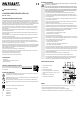

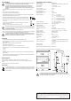

SAFETY INSTRUCTIONS
Please read all the instructions before using this device, they include important informa-
tion on its correct operation.
Damage caused by failure to follow these operating instructions will void the warranty/
guarantee! We do not assume any liability for any resulting damage!
We do not assume any liability for material and personal damage caused by improper
use or non-compliance with the safety instructions! In such cases, the warranty will be
null and void.
• This device left the factory in a safe and perfect condition.
• To tratain this condition an d to ensure safe operation, we kindly request the user to observe
the safety instructions and warnings contained in the enclosed operating n.
• The unauthorised conversion and/or modication of the unit is not permitted for safety and
approval reasons.
• Consult a professional if you are unsure how to operate the equipment or how to connect it
safely.
• Metrers and their accessories are not toys and should be kept out of the reach of children!
• In commercial institutions, the accident prevention regulations of the Employer’s Liability
Insurance Association for Electrical Systems and Operating Facilities are to be observed.
• In schools, training centres, hobby and your company support workshops, use of the measur-
ing device must be supervised by trained personnel in a responsible manner.
• Do not operate the device near to:
- strong magnetic or electromagnetic elds
- transmitting aerials or HF generators
These can affect the measurement.
• If you have reason to assume that safe operation is no longer possible, disconnect the device
immediately and secure it against inadvertent operation. Safe operation can no longer be
assumed if:
- the device is visibly damaged,
- the device does not function any more and
- the device was stored under unfavourable conditions for a long period of time or
- it has been subjected to considerable stress during transportation.
• Do not switch the measuring instrument on immediately after it has been taken from a cold
to a warm environment. The condensation that forms might destroy your device. Allow the
device to reach room temperature before switching it on.
• Do not leave packaging material carelessly lying around, as it could become a dangerous
plaything for children.
• You should also heed the safety instructions in each chapter of these instructions.
• The mounted instruments may not be used for medical purposes.
• Be especially cautious when dealing with voltages exceeding >33 V/AC or >70 V/DC! Even at
these voltages, there is a danger of fatal electric shock if you touch electric conductors.
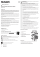
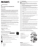
DESCRIPTION OF THE PARTS
1 Connecting terminal input
2 kWh display
3 Connecting terminal output
4 Locking and unlocking device for 35 mm DIN rails
5 Load display of the external conductor L1 (yellow),
L2 (green), L3 (red)
6 Metrological constant (LED)
7 Solderable terminal screw
INSTALLATION
• Lever out the unlocking device (4) with an appropriate slotted screwdriver for approx. 10 mm.
• Place the energy meter into correct position on the 35 mm rail.
• Slide the locking device (4) back into place. The energy meter is xed.
• Remove both terminal covers. For that, loosen the terminal screw (7).
1
2
3
7
5
6
7
4
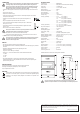
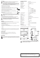
Operating Instructions
DPM-314D THREE-PHASE ENERGY METER
ITEM NO. 1386418
INTENDED USE
The energy metre is intended for installation in to control cabinets or sub-distribution units using 35 mm
DIN rail mounting as an indoor meter. The energy metere enables idisplay of the active energy consumed
in the three-phase four-wire electric installations with a reference current of 10 A (limiting current 100 A).
Energy consumption is displayed in kilowatts per hour (kWh) aggregated for all three external conductors.
LED display for each external conductor enables symmetrical load control.
A metrological constant is provided for further data acquisition. This LED ashes with an interval of 1000
pulses per kWh and can be used for tapping optional recording devices.
There is a digital display with 6 digits and 2 post-decimal digits. The display is blocked against rewind and
cannot be reset.
Connection is performed directly without any external components. Corresponding series resistors/current
shunts are already integrated.
The energy meter may only be put into use after it has been installed. The relevant regulations are to be
observed.
Front panel with display complies with tprotection class 2 and is touch-protected. The screw terminals must
be protected against touch by design (installation in sub-distribution units etc.).
The meter is not MID compliant and therefore may not be used for billing purposes.
Do not use this product in damp rooms or outdoors. For this purpose, relevant sub-distribution units with
moisture protection (IP54 class or higher) are to be used.
Operation in potentially explosive atmospheres (Ex) or wet areas or under adverse environmental condi-
tions is forbidden. Adverse environmental conditions are: Moisture or high humidity, dust and ammable
gases, fumes or solvents, as well as thunderstorms or thunderstorm conditions like strong electrostatic
elds etc.
No part of the product may be modied or converted!
The assembly and installation may only be carried out by a trained electrician who is familiar with the
relevant regulations and the potential hazards.
The safety instructions have to be followed without fail!
The specication data may not be exceeded.
PACKAGE CONTENTS
• Energy meter
• 2 terminal covers (mounted on the unit)
• Operating instructions
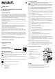
UP-TO-DATE OPERATING INSTRUCTIONS
Download the latest operating instructions at www.conrad.com/downloads or scan the
QR code shown. Follow the instructions on the website.
SYMBOL DESCRIPTION
An exclamation mark in a triangle indicates important information contained in these operating
instructions that must be observed by all means.
The lightning symbol in a triangle warns of electric shock danger or the impairment of the
electrical safety of the appliance.
The arrow symbol indicates special information and advice on operation.
This product has been CE tested and complies with national and European guidelines.
Protection Class 2 insulation (double or reinforced insulation).
Symbol for power supply type: 4-wire power supply
L1 external conductor L1
L2 external conductor L2
L3 external conductor L3
N neutral conductor N