
User manual

OS-10V 02/04/2001 Rev.2
5
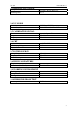
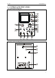
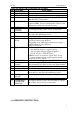
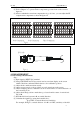
3.2 FUNCTIONS OF CONTROL SWITCHES
NO. SWITCHES FUNCTIONS
1 POWER SWITCH Power on/off.
2 POWER LIGHT Lights when power on.
3 INTENSITY Controls brightness of display.
4 FOCUS After obtaining appropriate brightness with INTENSITY,
adjust FOCUS for clearest line.
5 CALIBRATION Provide symmetric square wave for 0.5V range,
frequency=1KHz. Used for adjusting 10:1 Capacitor and
adjusting the vertical & horizontal sensitivity.
6 TIME/DIV Selects the sweep rate .
7 Horizontal
POSITION
Horizontal positioning control of trace on the screen.
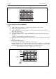
8 Time VAR Provides continuously variable sweep rate, turn clock wise
to the end is the calibrating position.
9 LEVEL Control signal trigger to sweep at certain level.
10 +/- ,
EXT/X
+: Triggering occurs when trigger signal crosses trigger
level in a positive-going direction.
-: Triggering occurs when trigger signal crosses trigger
level in a negative-going direction.
EXT/X: X-Y switch.
11 AUTO/NORM/
TV
AUTO : a single trace shown on screen even no signal.
Automatically reverts to triggered sweep
operation when adequate triggered signal is
present. Needs to adjust the Level.
NORM: No trace on screen if no signal. Trace is only
generated when adequate trigger signal is present
TV: used to show TV signals.
12 INT/EXT/LINE Switch to select the Trigger Source INT/EXT/LINE.
13 Ext. Trig Input
Terminal
When switching [10] to EXT/X, it’s X-Y input terminal;
When switching [12] to EXT, it’s Ext. Trig. Input terminal.
14 VOLTS/DIV Adjusting sensitivity of vertical system.
15 Vertical POSITION Control vertical position of trace on the screen.
16 Volt VAR Continuously adjusting the sensitivity of vertical system,
turn clockwise to the end is the calibration position.
17 coupling options
(AC⊥DC)
Selects input coupling options.
18 INPUT Vertical input terminal.
19 POWER INPUT
CONNECTOR
AND FUSE
power input connector (refer to the rear panel for voltage)
220 V ±10%; fuse 2 x 0.5A (on rear panel).
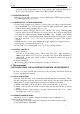
3.3 OPERATING INSTRUCTION