
User manual

OS-10V 02/04/2001 Rev.2
9
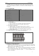
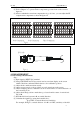
probe is 2V/DIV, then Vp-p=2×4.1=8.2(V)
Fig 4-3
4.2.2 DC VOLTAGE MEASUREMENT
STEP:
(1) Setup front panel connector to obtain a sweep baseline on the screen.
(2) Setup input coupling options as “⊥”.
(3) Setup POSITION, let sweep baseline coincide with horizontal center, define it as
zero reference level.
(4) Input signal into terminal.
(5) Set input coupling to “DC”, adjust VOLTS/DIV, let waveform show in the proper
position
on the screen, turn VAR to the calibration position.
(6) Read the divisions between the zero reference level to the wave form by the tested
object.
(7) Calculate the DC voltage:
V= divisions on vertical axis × sensitivity × direction(+/-)
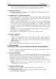
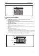
Shown in Figure 4-4, zero reference level at the center, use 10:1probe, sensitivity is
2V/Div, 2 points as A & B, A is 1.5 Div. over the zero reference level, B is 3Div.
below the zero reference level. DC voltage level of the 2 points are :
VA = 1.5 x 2 x (+) = 3 V VB = 3 x 2 x (-) = -6 V
Fig 4-4
A
B
B
A
Zero-volt
Reference
Level
Level