
Instructions
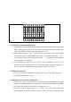
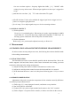
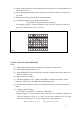
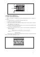
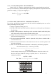

Table Of Contents

11
(5) Adjust vertical position to ensure the bottom of waveform lies on a horizontal axis on
the screen. Fig 4-3A.
(6) Adjust horizontal position to ensure the top of waveform lies center of vertical axis.
Fig 4-3B.
(7) Read the divisions between A-B on vertical direction.
(8) Calculate the signal Vp-p using the formula below :
Vp-p= DIV of vertical direction× Sensitivity
For example, In Fig 4-3, vertical divisions of A-B is 4.1 DIV, sensitivity of the 10:1
probe is 2V/DIV, then Vp-p=2×4.1=8.2(V)
Fig 4-3
4.2.2 DC VOLTAGE MEASUREMENT
STEP:
(1) Setup front panel connector to obtain a sweep baseline on the screen.
(2) Setup input coupling options as “⊥”.
(3) Setup POSITION, let sweep baseline to coincide with horizontal center, define it as
the zero reference level.
(4) Input signal into terminal.
(5) Set input coupling to “DC”, adjust VOLTS/DIV, so that the waveform is shown
centrally on the screen, turn VAR to the calibration position.
(6) Read the divisions between the zero reference level to the waveform from the test
input.
(7) Calculate the DC voltage:
V= divisions on vertical axis × sensitivity × direction(+/-)
Shown in Figure 4-4, zero reference level at the center, use 10:1probe, sensitivity is
2V/Div, 2 points as A & B, A is 1.5 Div. over the zero reference level, B is 3Div.
below the zero reference level. DC voltage level of the 2 points are :
VA = 1.5 x 2 x (+) = 3 V VB = 3 x 2 x (-) = -6 V
A
B