
User Guide


Page 9UG10637-1.0 - Inca 500 User Guide V1.0
Note: The rack mounting and desk/wall
mounting components described and
illustrated in Sections 4.1 to 4.3 are not supplied
with Inca 500 amplifiers but are available
to purchase as accessories. Contact sales@
voidacoustics.com for more information.
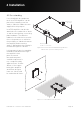
4.1 Inca 500 Mounting
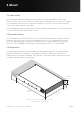
The Inca 500 amplifiers are shipped without
rack mount hardware attached but can be
configured for rack installation using one
standard rack ‘ear’ and one half-rack extension
piece as illustrated in figure 4.1. The
installation and equipment rack should
be configured to provide appropriate
ventilation airflow space around the sides
and rear of the amplifier as illustrated in as
illustrated in figure 3.1. Ventilation airflow
space of at least 25 mm (1 in) should be
maintained along at least one side of the
amplifier at all times. Ventilation apertures
are also located on the rear panel of the
amplifier and must not be obstructed. It is
important to retain at least 80 mm (3.1 in)
free space for airflow behind the amplifier
rear panel.
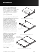
In addition to rack mount ears, optional
rack mount rear support hardware is
available and can be attached
to the amplifier. Rear support
hardware may be appropriate if the
amplifier is to be used in a mobile
rack or potentially be subject to
significant movement. Figure 4.2
illustrates the use of rack mount
rear support hardware.
Multiple Inca 500 amplifiers can
also be mechanically connected
using accessory connecting plates.
Figure 4.3 illustrates the use of
connecting plates.
4 Installation
Figure 4.1: Inca 500 Rack Ear + Half-rack Extension.
Rack Ear +
2 x M4 x 8 countersink
Half-rack Extension +
2 x M4 x 8 countersink
Figure 4.2: Inca 500 Rack Support hardware. 2 positions.
Rear Support + Button +
1 x M4 x 8
Connection Plate +
4 x M3 x 6 countersunk
Figure 4.3: 2 x Inca 500 with Connection Plate. 2 positions