
User Guide


Page 8UG10637-1.0 - Inca 500 User Guide V1.0
3 About
3.4 Connections
Inca 500 signal input and output connections are accomplished via RCA Phono and
Euroblock style connectors. A GPIO (General Purpose In/Out) Euroblock connector enables
some amplifier functions to be controlled, and wireless or RJ45 socket Ethernet network
connection options are also provided.
Inca 500 amplifiers have no mains power switch and are operational as soon as mains power
is connected via the IEC 60320 mains socket.
3.5 Network Features
Inca 500 amplifiers are TCP/IP network connected devices that require a wired or wireless
network connection to access their configuration menus. The configuration menus are
accessed via a web page interface and cover Input, Zone, Output and General Settings
functions. The configuration menus are fully described in Section 5 of this manual.
3.6 Dimensions
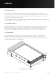
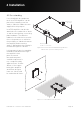
Inca 500 amplifier dimensions and features are illustrated in figure 3.1. The amplifiers are
primarily intended for installation in an equipment rack but can also be under-desk or
wall mounted, or used free standing. They are fan-cooled and must be installed such that
ventilation apertures are not obstructed.
44 mm
1.7 in
220 mm
8.7 in
80 mm
3.1 in
319 mm
12.6 in
25 mm
1.0 in
Figure 3.1: Inca 500 four channel amplifier dimensions.
Shaded area defines ventilation space.