
User Guide

Page 26UG10637-1.0 - Inca 500 User Guide V1.0
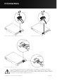
Once all connections have been made and configuration options selected, Inca 500
amplifiers are ready for use. If an input signal above -60dB is present on any input, the
front panel Input and Standby indicators will illuminate green to indicate normal amplifier
operation. Audio will be heard from any connected speakers.
Note: Inca 500 amplifiers will not switch on from Standby Mode unless an input signal is
present, a network ‘ON’ command is received, or an external standby switch (or 12V trigger)
is operated. Standby behaviour can be configured via the Power Management menu of the
Settings Tab.
Amplifier outputs will mute if no input signal is present for 5 minutes, and the amplifier will
switch automatically to Standby Mode if no signal is present on any input for more than
15 minutes. Alternative standby and mute delay times can selected via the Settings Tab.
Amplifier cooling fan speed is temperature controlled. The fan will switch o when the
amplifier enters standby mode.
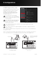
7.1 Front Panel Indicators
Inca 500 amplifier front panel indicators illuminate to indicate the following operational
states:
Status: O – Mains power disconnected.
Green – Amplifier operational.
Pulse Green – Standby Mode.
Amber – GPIO triggered Standby Mode
Input: O – No input signal present.
Green – Signal present on one or more inputs.
Amber – Signal limiting/clipping on one or more inputs.
Output: O – No output signal present.
Green – Signal present on one or more outputs.
Amber – Signal limiting/clipping on one or more outputs.
Red – One or more channel pair is in overload/protection mode.
Network: O – No Ethernet network detected.
Green – Ethernet network detected.
WiFi: O – WiFi disabled.
Green – WiFi enabled.
7 Operations