
User Guide

Page 25UG10637-1.0 - Inca 500 User Guide V1.0
5 mm
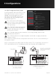
Low-Z Mode
Hi-Z Mode
5 mm
5 mm
5 mm
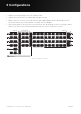
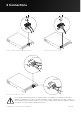
Figure 6.2: Balanced analog input cable connections.
Figure 6.4: Output cable connections.
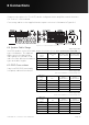
Figure 6.3: GPIO cable connections.
The exclamation point printed next to the output terminals of the amplifiers is, in addition to the CLASS 2
WIRING text, intended to alert users to the risk of hazardous voltages. Output connectors that could pose a
risk are marked with the exclamation point. Do not touch the output terminals while the amplifier is switched
on. Make all connections with the amplifier switched o.
6 Connections