
User Guide

Page 23UG10637-1.0 - Inca 500 User Guide V1.0
Output mode options (Lo-Z or Hi-Z) can be configured via the amplifier network interface.
See Section 5 of this manual.
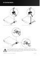
Connecting cables to the supplied female output connector is illustrated in Figure 6.4.
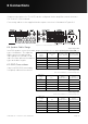
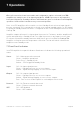
6.4 Speaker Cable Gauge
Inca 500 speaker connection cable gauge should be chosen appropriately to reflect the
type of installation. The adjacent
tables specify the appropriate
cable gauge for less than 0.5dB
cable loss with dierent installation
types and cable lengths.
6.5 GPIO Connections
If any Inca 500 GPIO functionality
is required, cables will need to be
Cable Gauge Table
Lo-Z installations. 4Ω & 8Ω loads
Cable Cross
Section
(mm
2
)
Cable Gauge
(US)
Max Cable Length
(metres, 4Ω load)
Max Cable Length
(metres, 8Ω load)
0.5 ≈20 2 5
0.75 ≈18 4 8
1.5 ≈16 6 12
2.0 ≈14 9 19
4.0 ≈12 14 30
Cable Gauge Table
70V Hi-Z installations. 60W & 125W power
Cable Cross
Section
(mm
2
)
Cable Gauge
(US)
Max Cable Length
(metres,
(125W/channel)
Max Cable Length
(metres,
(250W/channel)
0.5 ≈20 84 42
0.75 ≈18 132 66
1.5 ≈16 210 105
2.0 ≈14 334 166
4.0 ≈12 532 265
Cable Gauge Table
100V Hi-Z installations. 60W & 125W power
Cable Cross
Section
(mm
2
)
Cable Gauge
(US)
Max Cable Length
(metres,
(125W/channel)
Max Cable Length
(metres,
(250W/channel)
0.5 ≈20 171 85
0.75 ≈18 269 134
1.5 ≈16 430 215
2.0 ≈14 683 341
4.0 ≈12 1087 542
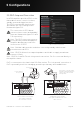
6 Connections
Figure 6.1: Inca 500 rear panel connections