
User Guide

Page 22UG10637-1.0 - Inca 500 User Guide V1.0
6 Connections
6.1 Mains Power Connection
Inca 500 amplifiers incorporate a power factor corrected universal power supply and can
be used with mains input voltage from 100V AC to 240V AC, 50/60Hz. Use the mains cable
supplied with the amplifier.
Inca 500 amplifiers have no mains power switch and are operational as soon as mains
power is connected. Ensure that all signal, GPIO and output connections are made before
connecting the amplifier to mains power.
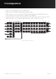
6.2 Input Connection
All Inca 500 amplifier models provide four balanced or unbalanced analog audio inputs and
a stereo S/PDIF digital audio input. Any input channel can be routed to any output channel.
Input routing options can be configured via the amplifier network interface. See Section 5
of this manual.
Analog Inputs
Inca 500 analog inputs are of line level format with a default input sensitivity of +4dBu (full
output voltage swing/sensitivity) in all output modes. Input signal levels up to +24dBu can
be handled without input clipping. Input sensitivity options can be set via the amplifier net-
work interface. See Section 5 of this manual.
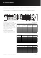
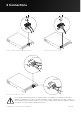
Balanced input connections to the amplifiers are made via male ‘Euro Block’ connectors.
Connecting cables to the supplied female input connectors is illustrated in figure 6.2.
Unbalanced input connections to the amplifiers are made via RCA phono sockets.
Digital Inputs
Inca 500 S/PDIF stereo digital audio input connections are made via a single RCA Phono
socket
Note: An S/PDIF digital audio output socket is also fitted. The S/PDIF output signal by
default reflects the input to amplifier installation zones A & B and is intended to be used for
daisy-chaining Inca 500 amplifiers.
Note: 75Ω RCA Phono cables specifically intended for digital audio should always be used
for S/PDIF connections.
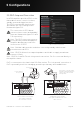
6.3 Output Connections
Output connections from the amplifiers are achieved via male ‘Euro Block’ connectors.
Ensure that speaker connection polarity is correct throughout the installation:
In the case of Lo-Z speaker connections, positive (+) amplifier terminals should always
be connected to positive speaker terminals and negative (–) amplifier terminals always
connected to negative speaker terminals.
In the case of Hi-Z speaker connections, the two speaker cable conductors should be
connected between the positive (+) terminal of Output 1 and the negative terminal (-) of
Output 2, and likewise for Outputs 3 and 4.