
User Guide

Page 21UG10637-1.0 - Inca 500 User Guide V1.0
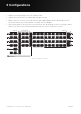
5.5 GPIO Setup and Connection
Inca 500 amplifiers provide a GPIO socket
that enables remote control of volume,
standby, mute and trigger functions.
The GPIO connector pin functions are
described in the GPIO Settings menu
illustrated in figure 5.12.
The connection of GPIO based
remote volume control and standby/
mute are illustrated in figure 5.10 and
5.11 respectively.
Note: The GPIO connector must not
be used for any unintended purpose.
Amplifier damage may result from
incorrect use of GPIO.
Note: Shielded cable must be used when connecting standby switches and
potentiometers via GPIO.
Note: GPIO Pin 8 has a low output impedance and is able to supply a maximum
current of 10mA.
Note: GPIO Pin 1 and Pin 3 both oer ground connections: Pin 1 is connected directly to
the amplifier chassis.
Pin 3 is connected to the chassis via a 220 Ohm resistor. The ‘soft ground’ connection of
Pin 3 is potentially useful for managing ground loops that may cause audible hum.
Figure 5.9: GPIO Settings Menu
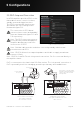
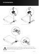
Figure 5.10: Potentiometer connections for
remote volume control via GPIO.
Note: Figure 6.3 illustrates
use of the GPIO connector.
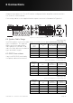
Figure 5.11: Connections for remote
standby/mute switch via GPIO.
Note: Figure 6.3 illustrates use of the
GPIO connector.
Ground
Standby/Mute
Ground
+3V3
Potentiometer
(>10kΩ)
Connect Wiper to
Pin 4, 5, 6 or 7.
Switch open or closed toggles
Standby or Mute depending on
options selected in the GPIO
Settings Menu
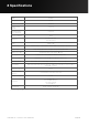
5 Configurations