
User Guide

Page 20UG10637-1.0 - Inca 500 User Guide V1.0
Analog 3
Output
Matrix
Zones A - D
Outputs 1 - 4
Analog 2
Input
Sensitivity
Analog 1
Input
Gain
Input
Sensitivity
Input
Gain
Input
Sensitivity
Input
Gain
Analog 4
SPDIF (stereo)
SPDIF Out (stereo).
Zones A (left) and B (right)
Pink Noise
Gain
Delay
Level
Adjustment
Level
Adjustment
Level
Adjustment
Level
Adjustment
Compressor
Compressor
Compressor
Compressor
Delay
Delay
Delay
EQ
EQ
EQ
EQ
EQ
EQ
EQ
EQ
FIR
FIR
FIR
FIR
Polarity
Polarity
Polarity
Polarity
Limiter
BTL
Amplifier
2 x Low-Z
1 x Hi-Z
BTL
Amplifier
2 x Low-Z
1 x Hi-Z
Limiter
Limiter
Limiter
Driver
Alignment
Driver
Alignment
Driver
Alignment
Driver
Alignment
Crossover
Crossover
Crossover
Crossover
Gain Trim
Gain Trim
Gain Trim
Gain Trim
Input
Sensitivity
Input
Gain
Input
Gain
Input
Selection
Input Setup
Zone Setup & Routing
Output Setup
Output 1
Output 2
Output 3
Output 4
Zone Adjustment Parameters
Speaker Preset Parameters
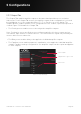
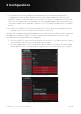
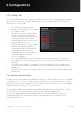
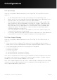
5 Configurations
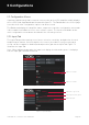
• Name zones by typing in the Zone Name field.
• Adjust the zone volume if required by using the slider.
• Define a mono or stereo zone by selecting the appropriate option. Defining a stereo
zone will reduce the total number of further zones available.
• Specify an input for the zone by selecting from the drop-down menu. Selecting a stereo
input for a mono zone will automatically sum the stereo channels to mono.
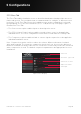
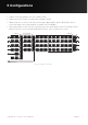
Figure 5.8: Signal Flow Schematic