voidacoustics.com Inca 500 Pro audio you can depend on USER GUIDE V1.
©2023 Void Acoustics Research Ltd. This user guide is subject to change without notice. For the latest online version, visit: www.voidacoustics.com Void Acoustics and the Void logo are registered trademarks of Void Acoustics Research Ltd. in the United Kingdom, USA and other countries; all other Void trademarks are the property of Void Acoustics Research Ltd.
Contents 1 Safety and Regulations 4 6 Connections 22 1.1 1.2 Important Safety Instructions 4 6.1 Main Power Connection 22 Limitations 4 6.2 Input Connection 22 1.3 EC Declaration of Conformity 4 6.3 Output Connections 22 1.4 UKCA Conformity 4 6.4 Speaker Cable Gauge 23 1.5 Warranty Statement 4 6.5 GPIO Connections 24 1.6 WEEE Directive 4 6.6 Network Connections 24 2 Unpacking and Checking 6 7 Operations 26 7.1 Front Panel Indicators 26 3 About 7 7.
1 Safety and Regulations 1.1 Important safety instructions The lightning flash with an arrowhead symbol within an equilateral triangle is intended to alert the user to the presence of uninsulated “dangerous voltage” within the product’s enclosure that may be of sufficient magnitude to constitute a risk of electric shock to persons.
Please read the following important technical, safety and environmental notices before installing and using your amplifier. Technical Notices All reasonable design and engineering steps have been taken to ensure that these amplifiers always perform satisfactorily in their intended application and environment and will provide appropriate levels of support to ensure that all reasonable customer needs and expectations are met. Such support however is contingent on the following provisions. 1.
2 Unpacking and Checking All Void Acoustics products are carefully manufactured and thoroughly tested before being despatched. Your dealer will ensure that your Void products are in pristine condition before being forwarded to you but mistakes and accidents can happen.
3 About 3.1 Welcome Many thanks for purchasing this Void Acoustics Inca Series amplifier. We truly appreciate your support. At Void, we design, manufacture and distribute advanced professional audio systems for the installed and live sound market sectors. Like all Void products, our highly skilled and experienced engineers have successfully combined pioneering technologies with groundbreaking design aesthetics, to bring you superior sound quality and visual innovation.
3 About 3.4 Connections Inca 500 signal input and output connections are accomplished via RCA Phono and Euroblock style connectors. A GPIO (General Purpose In/Out) Euroblock connector enables some amplifier functions to be controlled, and wireless or RJ45 socket Ethernet network connection options are also provided. Inca 500 amplifiers have no mains power switch and are operational as soon as mains power is connected via the IEC 60320 mains socket. 3.
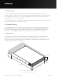
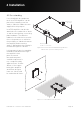
4 Installation Note: The rack mounting and desk/wall mounting components described and illustrated in Sections 4.1 to 4.3 are not supplied with Inca 500 amplifiers but are available to purchase as accessories. Contact sales@ voidacoustics.com for more information. Rack Ear + 2 x M4 x 8 countersink Half-rack Extension + 2 x M4 x 8 countersink 4.1 Inca 500 Mounting The Inca 500 amplifiers are shipped without rack mount hardware attached but can be configured for rack installation using one Figure 4.
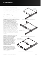
4 Installation 4.2 Free-standing If not installed in an equipment rack, Inca 500 amplifiers can be placed free-standing on a flat surface. Adhesive rubber feet are supplied for this purpose. Inca 500 amplifiers can also be attached to the underside of desks or wall mounted using connecting plate hardware. The adhesive rubber feet should also be used in these circumstances to minimise the possibility of vibration between the amplifier and mounting surface. Wall and desk mounting is illustrated in figure 4.
5 Configurations Before making input, output and GPIO connections, an initial Inca 500 amplifier configuration should be established. It is particularly important that the amplifier output format is configured appropriately for the speakers that are to be connected. Configuration requires that Inca 500 amplifiers are connected to mains power and network services. These connections are described in the following two sections. 5.
5 Configurations 5.2.2 Wireless (WiFi) Network Connection To connect an Inca 500 amplifier to a TCP/IP network using a wireless connection (WiFi) follow the steps below. 1. With the Inca 500 amplifier connected to mains power, wait for the front panel WiFi indicator to illuminate green. 2. Use a mobile, laptop or desktop device to search for available WiFi networks. Connect to, Inca 500 (product serial number)’ using the password, ‘password’. The amplifier serial number can be found on its rear panel. 3.
5 Configurations 5.3 Configuration Menus Opening a web browser that is network connected to an Inca 500 amplifier initially displays the Inca 500 Web App Dashboard illustrated in figure 5.1. The Dashboard is the ‘home’ page from which all other configuration options can be accessed. The Dashboard displays the amplifier status, output zones and the configuration menu tabs.
5 Configurations 5.3.2 Zone Tab The Zone Tab enables installation zones to be defined and named, and provides access to further sub-menus. Zones might be bar or restaurant areas for example, or different rooms in a home. For all Zone Tab menus, the installation zone under configuration is selected by highlighting one of the zone identifiers (A, B, C or D) at the top of the page. Figure 5.3 illustrates the Zone Tab. • The Source menu option enables inputs to be assigned to zones.
5 Configurations 5.3.3 Output Tab The Output Tab enables amplifier outputs to be named and provides access to further sub-menus. For all Output Tab menus, the amplifier output under configuration is selected by highlighting one of the output identifiers (1, 2, 3 or 4) at the top of the display. The Output Tab also enables Speaker Preset configurations to be created, exported, imported or cleared. Figure 5.4 illustrates the Output Tab. • The Routing menu enables zones to be assigned to amplifier outputs.
5 Configurations • The Speaker Preset menu enables speaker parameters to be adjusted, and preset configurations to be created. Speaker Presets can be simply applied to the selected amplifier output or exported, imported or cleared. The preset configurations can include any or all of the parameters described in the following paragraphs and can be protected to prevent inadvertent modification. Figures 5.5 to 5.7 illustrate the application of speaker presets.
5 Configurations 5.3.4 Speaker Preset Menu Parameters • The Crossover & Gain preset menu enables high or low-pass crossover filters and gain adjustment to be applied to individual amplifier outputs. • The Speaker EQ preset menu enables parametric equalization to be applied to individual amplifier outputs.
5 Configurations 5.3.5 Settings Tab The Settings Tab enables miscellaneous amplifier settings to be configured and installation data to be recorded. The Settings Tab provides access to further sub-menus. Figure 5.10 illustrates the Settings Tab. • • • • • • • The System Information menu provides text fields for the recording of installation data. The Device menu records amplifier specific information such as the model number and firmware version.
5 Configurations 5.4.1 Input Setup Open the configuration Dashboard and select the Input Tab. The Input Tab is shown in figure 5.2. • • • • To edit default input names simply select and type in the Input Name field. Define a mono or stereo input by selecting the appropriate option. Defining a stereo input will reduce the total number of discrete inputs available. Select an input sensitivity option from the drop-down menu: +14dB, +4dB, -10dB and ‘microphone’ options are available.
5 Configurations • Name zones by typing in the Zone Name field. • Adjust the zone volume if required by using the slider. • Define a mono or stereo zone by selecting the appropriate option. Defining a stereo zone will reduce the total number of further zones available. • Specify an input for the zone by selecting from the drop-down menu. Selecting a stereo input for a mono zone will automatically sum the stereo channels to mono.
5 Configurations 5.5 GPIO Setup and Connection Inca 500 amplifiers provide a GPIO socket that enables remote control of volume, standby, mute and trigger functions. The GPIO connector pin functions are described in the GPIO Settings menu illustrated in figure 5.12. The connection of GPIO based remote volume control and standby/ mute are illustrated in figure 5.10 and 5.11 respectively. Note: The GPIO connector must not be used for any unintended purpose.
6 Connections 6.1 Mains Power Connection Inca 500 amplifiers incorporate a power factor corrected universal power supply and can be used with mains input voltage from 100V AC to 240V AC, 50/60Hz. Use the mains cable supplied with the amplifier. Inca 500 amplifiers have no mains power switch and are operational as soon as mains power is connected. Ensure that all signal, GPIO and output connections are made before connecting the amplifier to mains power. 6.
6 Connections Output mode options (Lo-Z or Hi-Z) can be configured via the amplifier network interface. See Section 5 of this manual. Connecting cables to the supplied female output connector is illustrated in Figure 6.4. 6.4 Speaker Cable Gauge Figure 6.1: Inca 500 rear panel connections Cable Gauge Table Inca 500 speaker connection cable gauge should be chosen appropriately to reflect Lo-Z installations. 4Ω &the 8Ω loads type of installation.
6 Connections connected to the supplied GPIO connector. Connecting cables to the GPIO connector is illustrated in Figure 6.3. 6.6 Network Connections Inca 500 amplifiers are TCP/IP network connected devices that are configured via a web page based interface. Wired (Ethernet) and wireless (WiFi) connection options are available. Connecting Inca 500 amplifiers to a TCP/IP network is described in Section 5 of this manual. UG10637-1.0 - Inca 500 User Guide V1.
6 Connections 5 mm 5 mm Figure 6.2: Balanced analog input cable connections. Figure 6.3: GPIO cable connections. Low-Z Mode 5 mm Hi-Z Mode 5 mm Figure 6.4: Output cable connections. The exclamation point printed next to the output terminals of the amplifiers is, in addition to the CLASS 2 WIRING text, intended to alert users to the risk of hazardous voltages. Output connectors that could pose a risk are marked with the exclamation point.
7 Operations Once all connections have been made and configuration options selected, Inca 500 amplifiers are ready for use. If an input signal above -60dB is present on any input, the front panel Input and Standby indicators will illuminate green to indicate normal amplifier operation. Audio will be heard from any connected speakers.
7 Operations 7.2 Automatic Power Sharing Inca 500 amplifiers incorporate a power sharing feature that automatically shares the total power available from the amplifier’s internal power supply across each pair of output channels. If one channel temporarily demands more than the amplifier’s continuous power rating while other channel is demanding less, the excess power available from the internal power supply is automatically made available to the over-power channel.
8 Specifications Model Inca 500 Total System Power 500 W Output Power @ 4/8Ω 4 x 125 W Output Power @ 70/100V* 2 x 250 W Powershare (up to) Across all channels 2 x 250 W Power Consumption 150W 44 x 220 x 319 mm (1.7 x 8.7 x 12.6 in) Dimensions Weight 2.8kg (6.
NORTH AMERICA Void Acoustics North America Call: +1 503 854 7134 Email: sales.usa@voidacoustics.com HEAD OFFICE Void Acoustics Research Ltd, Unit 15, Dawkins Road Industrial Estate, Poole, Dorset, BH15 4JY United Kingdom Call: +44(0) 1202 666006 Email: info@voidacoustics.com voidacoustics.