
Service manual


HEC-Series Service Manual
INSTALLING YOUR TUBE-ICE MACHINE
10/21/01
3-5
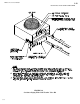
Piping and Drain Connections. All connections are located at the rear of the machine. Look for
four water connections on the freezing unit of each water cooled machine. See Space Diagram,
FIGURE 3-4 for correct utility connections.
! CAUTION !
Exterior shut-off valves must be provided in the water inlet lines.
The minimum inlet water pressure for
satisfactory operation of the machine is 30 psig.
The maximum allowable pressure is 100 psig.
! CAUTION !
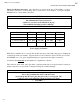
Model HEC-10 HEC-20 HEC-30 HEC-40
Make Up Water In 3/8” FPT 3/8” FPT 3/8” FPT 3/8” FPT
Water Tank Drain 3/4” FPT 3/4” FPT 3/4” FPT 3/4” FPT
Condenser Water In 3/4” FPT 3/4” FPT 3/4” FPT 1” FPT
Condenser Water Out
3/4” FPT 3/4” FPT 3/4” FPT 1” FPT
TABLE 3-1
Water Supply and Drains
When the ice machine sits on a storage bin, the bin must be provided with a drip pan for catching the
condensate from the ice machine. Separate drains for the condensate and for the bin are necessary.
See FIGURE 3-4 or 3-5 (space diagram drawings for typical water and drain connections).
Condensate drain must not run through the ice compartment of the bin.
The condenser water outlet, water pan drain, condensate drain and ice storage bin drain connections
must be extended to an open drain or sump and arranged for visible discharge.
! CAUTION !
These lines must NOT be connected into a pressure tight common header
due to the possibility that warm condenser water
may back up into the water pan, drip pan or the ice storage bin. The
condenser water outlet MUST be piped separately to the drain.
! CAUTION !