
6.7

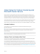
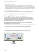
Table Of Contents
- Setup for Failover Clustering and Microsoft Cluster Service
- Contents
- About Setup for Failover Clustering and Microsoft Cluster Service
- Getting Started with MSCS
- Clustering Configuration Overview
- Hardware and Software Requirements for Clustering
- Supported Shared Storage Configurations
- PSP_RR Support for MSCS
- iSCSI Support for MSCS
- FCoE Support for MSCS
- vMotion support for MSCS
- VVol Support for MSCS
- vSphere MSCS Setup Limitations
- MSCS and Booting from a SAN
- Set up CCR and DAG Groups
- Setting up AlwaysOn Availability Groups with SQL Server 2012
- Cluster Virtual Machines on One Physical Host
- Cluster Virtual Machines Across Physical Hosts
- Create the First Node for MSCS Clusters Across Physical Hosts
- Create Additional Nodes for Clusters Across Physical Hosts
- Add Hard Disks to the First Node for Clusters Across Physical Hosts
- Add Hard Disks to the First Node for Clusters Across Physical Hosts with VVol
- Add Hard Disks to Additional Nodes for Clusters Across Physical Hosts
- Cluster Physical and Virtual Machines
- Use MSCS in an vSphere HA and vSphere DRS Environment
- vSphere MSCS Setup Checklist

A typical clustering setup includes:
n
Disks that are shared between nodes. A shared disk is required as a quorum disk. In a cluster of
virtual machines across physical hosts, the shared disk must be on a Fibre Channel (FC) SAN, FCoE
or iSCSI. A quorum disk must have a homogenous set of disks. This means that if the configuration is
done with FC SAN, then all of the cluster disks should be FC SAN only. Mixed mode is not supported.
n
A private heartbeat network between nodes.
You can set up the shared disks and private heartbeat using one of several clustering configurations.
In ESXi 6.7, MSCS pass-through support for VVols (Virtual Volumes) permits the shared disk to be on a
VVol storage that supports SCSI Persistent Reservations for VVols.
Clustering MSCS Virtual Machines on a Single Host
A cluster of MSCS virtual machines on a single host (also known as a cluster in a box) consists of
clustered virtual machines on the same ESXi host. The virtual machines are connected to the same
storage, either local or remote. This configuration protects against failures at the operating system and
application level, but it does not protect against hardware failures.
Note Windows Server 2008 R2 and above releases support up to five nodes (virtual machines).
Windows Server 2003 SP2 systems support two nodes.
The following figure shows a cluster in a box setup.
n
Two virtual machines on the same physical machine (ESXi host) run clustering software.
n
The virtual machines share a private network connection for the private heartbeat and a public
network connection.
n
Each virtual machine is connected to shared storage, which can be local or on a SAN.
Figure 1‑1. Virtual Machines Clustered on a Single Host
physical machine
virtual machine
Node1
cluster
software
virtual machine
Node2
cluster
software
storage (local or SAN)
private
network
public
network
Setup for Failover Clustering and Microsoft Cluster Service
VMware, Inc. 7