
1.0
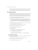
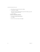
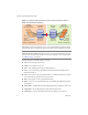
Table Of Contents
- Administration Guide
- Contents
- About This Book
- Overview of Site Recovery Manager
- System Requirements
- Installing or Updating Site Recovery Manager
- Managing SRM
- Protected Site Configuration
- Recovery Site Configuration
- Failback
- Alerting and Monitoring
- Protected and Recovery Site Changes
- Preinstallation Checklist
- Failback Checklist
- Use the srm-config command to repair an SRM server connection
- Avoiding Replication of Paging Files and Other Transient Data
- Glossary
- Index

Site Recovery Manager Administration Guide
70 VMware, Inc.
Figure 7-1. Storage Configuration after Running an Actual Failover from Site A to
Site B for the shared-san-2 Datastore
ThisfailbackscenariodescribesthestepsforasuccessfulfailbackfromSiteBtoSiteA.
ItincludesthestepstocompletethereprotectionofSiteAafterthefailbackfromSiteB.
Thefollowingtermsandabbreviationsareused.
SiteA—Theoriginalprotectedsite.
SiteB—Theoriginalrecoverysite.
PG1—TheoriginalprotectiongroupdefinedatSiteA.
PG2—AnewprotectiongroupdefinedatSiteBtofacilitatethefailbackfrom
Site BbacktoSiteA.
PG3—AnewprotectiongroupdefinedatSiteAtofacilitatethefailovertoSiteB.
PG3isbasicallythesameprotectiongroupasPG1.
RP1—TheoriginalrecoveryplandefinedatSiteB.
RP2—AnewrecoveryplandefinedatSiteAtofacilitatethefailbackfromSiteB
backtoSiteA.
SourceLUN—AVMFSdatastorethatisbeingreplicatedtoanalternativedatacenter .
TargetLUN—Theresultingdatastoreatthealternatedatacenter.
CloneLUN—AcloneofthetargetLUNusedonlyduringatestoffailover.
NOTEIfyouhavenotpurchasedaprotection‐enablementlicensekey
(SRM_PROTECTED_HOST)fortheprotectedsite,youmusttransferthatkeyfromthe
recoverysitetotheprotectedsitebeforeyoucanrunafailback.Formoreinformation,
see“SRMLicensing”onpage 24
Site A — protected site Site B — recovery site
source LUN
(shared-san-2)
Write Disabled
(read only)
target LUN
(shared-san-2)
Read Write
enabled
protected
virtual machines
(app_vm7 to app_vm12)
apps
apps
apps
apps
apps
apps
OS
apps
apps
apps
apps
apps
apps
OS
all
powered
off by SRM
at start of
SRM Recovery
protected
virtual machines
(app_vm7 to app_vm12)
all
powered
on by SRM
during the
SRM Recovery