
6.0.1

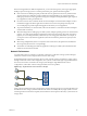


Table Of Contents
- vSphere Storage
- Contents
- About vSphere Storage
- Updated Information
- Introduction to Storage
- Overview of Using ESXi with a SAN
- Using ESXi with Fibre Channel SAN
- Configuring Fibre Channel Storage
- Configuring Fibre Channel over Ethernet
- Booting ESXi from Fibre Channel SAN
- Booting ESXi with Software FCoE
- Best Practices for Fibre Channel Storage
- Using ESXi with iSCSI SAN
- Configuring iSCSI Adapters and Storage
- ESXi iSCSI SAN Requirements
- ESXi iSCSI SAN Restrictions
- Setting LUN Allocations for iSCSI
- Network Configuration and Authentication
- Set Up Independent Hardware iSCSI Adapters
- About Dependent Hardware iSCSI Adapters
- Dependent Hardware iSCSI Considerations
- Configure Dependent Hardware iSCSI Adapters
- About the Software iSCSI Adapter
- Modify General Properties for iSCSI Adapters
- Setting Up iSCSI Network
- Using Jumbo Frames with iSCSI
- Configuring Discovery Addresses for iSCSI Adapters
- Configuring CHAP Parameters for iSCSI Adapters
- Configuring Advanced Parameters for iSCSI
- iSCSI Session Management
- Booting from iSCSI SAN
- Best Practices for iSCSI Storage
- Managing Storage Devices
- Storage Device Characteristics
- Understanding Storage Device Naming
- Storage Refresh and Rescan Operations
- Identifying Device Connectivity Problems
- Edit Configuration File Parameters
- Enable or Disable the Locator LED on Storage Devices
- Working with Flash Devices
- About VMware vSphere Flash Read Cache
- Working with Datastores
- Understanding VMFS Datastores
- Understanding Network File System Datastores
- Creating Datastores
- Managing Duplicate VMFS Datastores
- Upgrading VMFS Datastores
- Increasing VMFS Datastore Capacity
- Administrative Operations for Datastores
- Set Up Dynamic Disk Mirroring
- Collecting Diagnostic Information for ESXi Hosts on a Storage Device
- Checking Metadata Consistency with VOMA
- Configuring VMFS Pointer Block Cache
- Understanding Multipathing and Failover
- Raw Device Mapping
- Working with Virtual Volumes
- Virtual Machine Storage Policies
- Upgrading Legacy Storage Profiles
- Understanding Virtual Machine Storage Policies
- Working with Virtual Machine Storage Policies
- Creating and Managing VM Storage Policies
- Storage Policies and Virtual Machines
- Default Storage Policies
- Assign Storage Policies to Virtual Machines
- Change Storage Policy Assignment for Virtual Machine Files and Disks
- Monitor Storage Compliance for Virtual Machines
- Check Compliance for a VM Storage Policy
- Find Compatible Storage Resource for Noncompliant Virtual Machine
- Reapply Virtual Machine Storage Policy
- Filtering Virtual Machine I/O
- VMkernel and Storage
- Storage Hardware Acceleration
- Hardware Acceleration Benefits
- Hardware Acceleration Requirements
- Hardware Acceleration Support Status
- Hardware Acceleration for Block Storage Devices
- Hardware Acceleration on NAS Devices
- Hardware Acceleration Considerations
- Storage Thick and Thin Provisioning
- Using Storage Providers
- Using vmkfstools
- vmkfstools Command Syntax
- vmkfstools Options
- -v Suboption
- File System Options
- Virtual Disk Options
- Supported Disk Formats
- Creating a Virtual Disk
- Example for Creating a Virtual Disk
- Initializing a Virtual Disk
- Inflating a Thin Virtual Disk
- Removing Zeroed Blocks
- Converting a Zeroedthick Virtual Disk to an Eagerzeroedthick Disk
- Deleting a Virtual Disk
- Renaming a Virtual Disk
- Cloning or Converting a Virtual Disk or RDM
- Example for Cloning or Converting a Virtual Disk
- Migrate Virtual Machines Between DifferentVMware Products
- Extending a Virtual Disk
- Upgrading Virtual Disks
- Creating a Virtual Compatibility Mode Raw Device Mapping
- Example for Creating a Virtual Compatibility Mode RDM
- Creating a Physical Compatibility Mode Raw Device Mapping
- Listing Attributes of an RDM
- Displaying Virtual Disk Geometry
- Checking and Repairing Virtual Disks
- Checking Disk Chain for Consistency
- Storage Device Options
- Index

When writing data to storage, multiple systems or virtual machines might aempt to ll their links. As
Dropped Packets shows, when this happens, the switch between the systems and the storage system has to
drop data. This happens because, while it has a single connection to the storage device, it has more trac to
send to the storage system than a single link can carry. In this case, the switch drops network packets
because the amount of data it can transmit is limited by the speed of the link between it and the storage
system.
Figure 12‑2. Dropped Packets
1 Gbit
1 Gbit
1 Gbit
dropped packets
Recovering from dropped network packets results in large performance degradation. In addition to time
spent determining that data was dropped, the retransmission uses network bandwidth that could otherwise
be used for current transactions.
iSCSI trac is carried on the network by the Transmission Control Protocol (TCP). TCP is a reliable
transmission protocol that ensures that dropped packets are retried and eventually reach their destination.
TCP is designed to recover from dropped packets and retransmits them quickly and seamlessly. However,
when the switch discards packets with any regularity, network throughput suers signicantly. The
network becomes congested with requests to resend data and with the resent packets, and less data is
actually transferred than in a network without congestion.
Most Ethernet switches can buer, or store, data and give every device aempting to send data an equal
chance to get to the destination. This ability to buer some transmissions, combined with many systems
limiting the number of outstanding commands, allows small bursts from several systems to be sent to a
storage system in turn.
If the transactions are large and multiple servers are trying to send data through a single switch port, a
switch's ability to buer one request while another is transmied can be exceeded. In this case, the switch
drops the data it cannot send, and the storage system must request retransmission of the dropped packet.
For example, if an Ethernet switch can buer 32KB on an input port, but the server connected to it thinks it
can send 256KB to the storage device, some of the data is dropped.
Most managed switches provide information on dropped packets, similar to the following:
*: interface is up
IHQ: pkts in input hold queue IQD: pkts dropped from input queue
OHQ: pkts in output hold queue OQD: pkts dropped from output queue
RXBS: rx rate (bits/sec) RXPS: rx rate (pkts/sec)
TXBS: tx rate (bits/sec) TXPS: tx rate (pkts/sec)
TRTL: throttle count
Table 12‑1. Sample Switch Information
Interface IHQ IQD OHQ OQD RXBS RXPS TXBS TXPS TRTL
*
GigabitEt
hernet0/1
3 9922 0 0 47630300
0
62273 47784000
0
63677 0
In this example from a Cisco switch, the bandwidth used is 476303000 bits/second, which is less than half of
wire speed. In spite of this, the port is buering incoming packets and has dropped quite a few packets. The
nal line of this interface summary indicates that this port has already dropped almost 10,000 inbound
packets in the IQD column.
vSphere Storage
118 VMware, Inc.