
4.2
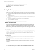
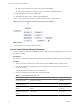
Table Of Contents
- Developing with VMware vCenter Orchestrator
- Contents
- Developing with VMware vCenter Orchestrator
- Updated Information
- Developing Workflows
- Principal Phases in the Workflow Development Process
- Accessing the Orchestrator Client
- Testing Workflows During Development
- Workflow Editor
- Provide General Workflow Information
- Defining Attributes and Parameters
- Workflow Schema
- Obtaining Input Parameters from Users When a Workflow Starts
- Requesting User Interactions While a Workflow Runs
- Add a User Interaction to a Workflow
- Set the User Interaction security.group Attribute
- Set the timeout.date Attribute to an Absolute Date
- Calculate a Relative Timeout for User Interactions
- Set the timeout.date Attribute to a Relative Date
- Define the External Inputs for a User Interaction
- Define User Interaction Exception Behavior
- Create the Input Parameters Dialog Box for the User Interaction
- Respond to a Request for a User Interaction
- Calling Workflows Within Workflows
- Running a Workflow on a Selection of Objects
- Developing Long-Running Workflows
- Configuration Elements
- Workflow User Permissions
- Validating Workflows
- Running Workflows
- Develop a Simple Example Workflow
- Create the Simple Workflow Example
- Define the Simple Workflow Example Parameters
- Create the Simple Workflow Example Schema
- Link the Simple Workflow Example Elements
- Create Workflow Zones
- Define the Simple Workflow Example Decision Bindings
- Bind the Simple Workflow Example Action Elements
- Bind the Simple Workflow Example Scripted Task Elements
- Define the Simple Example Workflow Exception Bindings
- Set the Simple Workflow Example Attribute Read-Write Properties
- Set the Simple Workflow Example Parameter Properties
- Set the Layout of the Simple Workflow Example Input Parameters Dialog Box
- Validate and Run the Simple Workflow Example
- Develop a Complex Workflow
- Create the Complex Workflow
- Define the Complex Workflow Example Input Parameters
- Create a Custom Action For the Complex Workflow Example
- Create the Complex Workflow Example Schema
- Link the Complex Workflow Example Schema Elements
- Create the Complex Workflow Example Zones
- Define the Complex Workflow Example Bindings
- Set the Complex Workflow Example Attribute Properties
- Create the Layout of the Complex Workflow Example Input Parameters
- Validate and Run the Complex Workflow Example
- Scripting
- Orchestrator Elements that Require Scripting
- Limitations of the Mozilla Rhino Implementation in Orchestrator
- Using the Orchestrator API
- Access the Scripting Engine from the Workflow Editor
- Access the Scripting Engine from the Action or Policy Editor
- Access the Orchestrator API Explorer
- Use the Orchestrator API Explorer to Find Objects
- Writing Scripts
- Add Parameters to Scripts
- Accessing the Orchestrator Server File System from JavaScript and Workflows
- Accessing Java Classes from JavaScript
- Accessing Operating System Commands from JavaScript
- Exception Handling Guidelines
- Orchestrator JavaScript Examples
- Developing Actions
- Creating Resource Elements
- Creating Packages
- Index

n
Drag a scripted element to the right of OK and name it Send Email.
n
Drag a scripted element to the right of Timeout 2 and name it Send Email Failed.
13 Drag an end element to the right of Send Email.
14 Click Save at the bottom of the workflow editor Schema tab.
Figure 1-3 shows the layout of the Start VM and Send Email workflow schema elements.
Figure 1-3. Start VM and Send Email Example Workflow Schema Elements
What to do next
You must now link the workflow elements together.
Link the Simple Workflow Example Elements
You link a workflow's elements in the Schema tab of the workflow editor. The linking defines the flow of data
through the workflow.
Prerequisites
You must have created the Start VM and Send Email workflow, defined its parameters, and laid out its schema.
Procedure
1 Click the connector tool button in the toolbar at the top of the Schema tab in the workflow editor.
2 Click the start element, and holding the left mouse button down, move the pointer to the VM Powered
On? decision element.
You have linked the start element to the decision element.
3 Link the remaining elements as described in the following table.
Table 1-7. Simple Workflow Example Links
Click Link to Type of Arrow Description
Left side of VM Powered
On? decision element
Already Started
scriptable task element
Green Input matches decision
statement
Right side of VM Powered
On? decision element
startVM action element Red dotted Input does not match
decision statement
Middle of startVM action
element
vim3WaitTaskEnd action
element
Black Normal workflow
progression
Middle of
vim3WaitTaskEnd action
element
vim3WaitToolsStarted
action element
Black Normal workflow
progression
Developing with VMware vCenter Orchestrator
70 VMware, Inc.