
4.2
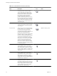
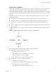
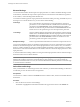
Table Of Contents
- Developing with VMware vCenter Orchestrator
- Contents
- Developing with VMware vCenter Orchestrator
- Updated Information
- Developing Workflows
- Principal Phases in the Workflow Development Process
- Accessing the Orchestrator Client
- Testing Workflows During Development
- Workflow Editor
- Provide General Workflow Information
- Defining Attributes and Parameters
- Workflow Schema
- Obtaining Input Parameters from Users When a Workflow Starts
- Requesting User Interactions While a Workflow Runs
- Add a User Interaction to a Workflow
- Set the User Interaction security.group Attribute
- Set the timeout.date Attribute to an Absolute Date
- Calculate a Relative Timeout for User Interactions
- Set the timeout.date Attribute to a Relative Date
- Define the External Inputs for a User Interaction
- Define User Interaction Exception Behavior
- Create the Input Parameters Dialog Box for the User Interaction
- Respond to a Request for a User Interaction
- Calling Workflows Within Workflows
- Running a Workflow on a Selection of Objects
- Developing Long-Running Workflows
- Configuration Elements
- Workflow User Permissions
- Validating Workflows
- Running Workflows
- Develop a Simple Example Workflow
- Create the Simple Workflow Example
- Define the Simple Workflow Example Parameters
- Create the Simple Workflow Example Schema
- Link the Simple Workflow Example Elements
- Create Workflow Zones
- Define the Simple Workflow Example Decision Bindings
- Bind the Simple Workflow Example Action Elements
- Bind the Simple Workflow Example Scripted Task Elements
- Define the Simple Example Workflow Exception Bindings
- Set the Simple Workflow Example Attribute Read-Write Properties
- Set the Simple Workflow Example Parameter Properties
- Set the Layout of the Simple Workflow Example Input Parameters Dialog Box
- Validate and Run the Simple Workflow Example
- Develop a Complex Workflow
- Create the Complex Workflow
- Define the Complex Workflow Example Input Parameters
- Create a Custom Action For the Complex Workflow Example
- Create the Complex Workflow Example Schema
- Link the Complex Workflow Example Schema Elements
- Create the Complex Workflow Example Zones
- Define the Complex Workflow Example Bindings
- Set the Complex Workflow Example Attribute Properties
- Create the Layout of the Complex Workflow Example Input Parameters
- Validate and Run the Complex Workflow Example
- Scripting
- Orchestrator Elements that Require Scripting
- Limitations of the Mozilla Rhino Implementation in Orchestrator
- Using the Orchestrator API
- Access the Scripting Engine from the Workflow Editor
- Access the Scripting Engine from the Action or Policy Editor
- Access the Orchestrator API Explorer
- Use the Orchestrator API Explorer to Find Objects
- Writing Scripts
- Add Parameters to Scripts
- Accessing the Orchestrator Server File System from JavaScript and Workflows
- Accessing Java Classes from JavaScript
- Accessing Operating System Commands from JavaScript
- Exception Handling Guidelines
- Orchestrator JavaScript Examples
- Developing Actions
- Creating Resource Elements
- Creating Packages
- Index

What to do next
The elements are joined, but you have not defined the data flow. You must define the IN and OUT bindings
to bind incoming and outgoing data to workflow attributes.
Data Flow of a Workflow
The data flow of a workflow is the manner in which workflow element input and output parameters bind to
workflow attributes as each element of the workflow runs. You define the data flow of a workflow by using
schema element bindings.
When an element in the workflow schema runs, it requires data in the form of input parameters. It takes the
data for its input parameters by binding to a workflow attribute that you set when you create the workflow,
or by binding to an attribute that a preceding element in the workflow set when it ran.
The element processes the data, possibly transforms it, and generates the results of its run in the form of output
parameters. The element binds its resulting output parameters to new workflow attributes that it creates. Other
elements in the schema can bind to these new workflow attributes as their input parameters. The workflow
can generate the attributes as its output parameters at the end of its run.
Figure 1-2 shows a very simple workflow. The black arrows represent the element linking and the logical flow
of the workflow. The red lines show the data flow of the workflow.
Figure 1-2. Example of Workflow Data Flow
The data flows through the workflow as follows.
1 The workflow starts with input parameters a and b.
2 The first element processes parameter a and binds the result of the processing to workflow attribute c.
3 The first element processes parameter b and binds the result of the processing to workflow attribute d.
4 The second element takes workflow attribute c as an input parameter, processes it, and binds the resulting
output parameter to workflow attribute e.
5 The second element takes workflow attribute d as an input parameter, processes it, and generates output
parameter f.
6 The workflow ends and generates workflow attribute f as its output parameter, the result of its run.
Chapter 1 Developing Workflows
VMware, Inc. 29