
4.2
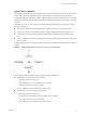
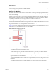
Table Of Contents
- Developing with VMware vCenter Orchestrator
- Contents
- Developing with VMware vCenter Orchestrator
- Updated Information
- Developing Workflows
- Principal Phases in the Workflow Development Process
- Accessing the Orchestrator Client
- Testing Workflows During Development
- Workflow Editor
- Provide General Workflow Information
- Defining Attributes and Parameters
- Workflow Schema
- Obtaining Input Parameters from Users When a Workflow Starts
- Requesting User Interactions While a Workflow Runs
- Add a User Interaction to a Workflow
- Set the User Interaction security.group Attribute
- Set the timeout.date Attribute to an Absolute Date
- Calculate a Relative Timeout for User Interactions
- Set the timeout.date Attribute to a Relative Date
- Define the External Inputs for a User Interaction
- Define User Interaction Exception Behavior
- Create the Input Parameters Dialog Box for the User Interaction
- Respond to a Request for a User Interaction
- Calling Workflows Within Workflows
- Running a Workflow on a Selection of Objects
- Developing Long-Running Workflows
- Configuration Elements
- Workflow User Permissions
- Validating Workflows
- Running Workflows
- Develop a Simple Example Workflow
- Create the Simple Workflow Example
- Define the Simple Workflow Example Parameters
- Create the Simple Workflow Example Schema
- Link the Simple Workflow Example Elements
- Create Workflow Zones
- Define the Simple Workflow Example Decision Bindings
- Bind the Simple Workflow Example Action Elements
- Bind the Simple Workflow Example Scripted Task Elements
- Define the Simple Example Workflow Exception Bindings
- Set the Simple Workflow Example Attribute Read-Write Properties
- Set the Simple Workflow Example Parameter Properties
- Set the Layout of the Simple Workflow Example Input Parameters Dialog Box
- Validate and Run the Simple Workflow Example
- Develop a Complex Workflow
- Create the Complex Workflow
- Define the Complex Workflow Example Input Parameters
- Create a Custom Action For the Complex Workflow Example
- Create the Complex Workflow Example Schema
- Link the Complex Workflow Example Schema Elements
- Create the Complex Workflow Example Zones
- Define the Complex Workflow Example Bindings
- Set the Complex Workflow Example Attribute Properties
- Create the Layout of the Complex Workflow Example Input Parameters
- Validate and Run the Complex Workflow Example
- Scripting
- Orchestrator Elements that Require Scripting
- Limitations of the Mozilla Rhino Implementation in Orchestrator
- Using the Orchestrator API
- Access the Scripting Engine from the Workflow Editor
- Access the Scripting Engine from the Action or Policy Editor
- Access the Orchestrator API Explorer
- Use the Orchestrator API Explorer to Find Objects
- Writing Scripts
- Add Parameters to Scripts
- Accessing the Orchestrator Server File System from JavaScript and Workflows
- Accessing Java Classes from JavaScript
- Accessing Operating System Commands from JavaScript
- Exception Handling Guidelines
- Orchestrator JavaScript Examples
- Developing Actions
- Creating Resource Elements
- Creating Packages
- Index
n
true decision result, exception.
a The decision element returns true.
b The SnapVMsInResourcePool workflow encounters an error.
c The workflow returns an exception and stops in the failed state.
n
false decision result, exception.
a The decision element returns false.
b The operation the Scriptable task element defines encounters an error.
c The workflow returns an exception and stops in the failed state.
Element Links
Links connect schema elements and define the logical flow of the workflow from one element to the next.
Elements can usually set only one outgoing link to another element in the workflow and one exception link to
an element that defines its exception behavior. The outgoing link defines the standard path of the workflow.
The exception link defines the exception path of the workflow. In most cases, a single schema element can
receive incoming standard path links from multiple elements.
The following elements are exceptions to the preceding statements.
n
The Start Workflow element cannot receive incoming links and has no exception link.
n
Exception elements can receive multiple incoming exception links, and have no outgoing or exception
links.
n
Decision elements have two outgoing links that define the paths the workflow takes depending on the
decision's true or false result. Decisions have no exception link.
n
End Workflow elements cannot have outgoing links or exception links.
Create Standard Path Links
You link elements by connecting them using the connector tool in the Schema tab of the workflow editor.
When you link one element to another, you always link the elements in the order in which they run in the
workflow. You always start from the element that runs first to create a link between two elements.
Prerequisites
To link elements, you must have the workflow editor open and the Schema must contain elements.
Procedure
1 Click the connector tool button in the toolbar at the top of the Schema tab to activate the connector tool.
2 Click an element to link to another element.
3 Move the pointer over the highlighted element to link to another element.
A black rectangle appears at the bottom of the element.
4 Left-click inside the element near the black rectangle, hold down the left mouse button, and move the
pointer to the target element.
An arrow appears between the two elements and the target element turns green.
5 Release the left mouse button.
The arrow remains between the two elements.
A standard path now links the elements.
Developing with VMware vCenter Orchestrator
28 VMware, Inc.