
4.2.1
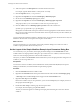
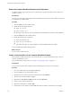
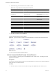
Table Of Contents
- Developing with VMware vCenter Orchestrator
- Contents
- Developing with VMware vCenter Orchestrator
- Developing Workflows
- Principal Phases in the Workflow Development Process
- Accessing the Orchestrator Client
- Testing Workflows During Development
- Workflow Editor
- Provide General Workflow Information
- Defining Attributes and Parameters
- Workflow Schema
- Obtaining Input Parameters from Users When a Workflow Starts
- Requesting User Interactions While a Workflow Runs
- Add a User Interaction to a Workflow
- Set the User Interaction security.group Attribute
- Set the timeout.date Attribute to an Absolute Date
- Calculate a Relative Timeout for User Interactions
- Set the timeout.date Attribute to a Relative Date
- Define the External Inputs for a User Interaction
- Define User Interaction Exception Behavior
- Create the Input Parameters Dialog Box for the User Interaction
- Respond to a Request for a User Interaction
- Calling Workflows Within Workflows
- Running a Workflow on a Selection of Objects
- Developing Long-Running Workflows
- Configuration Elements
- Workflow User Permissions
- Validating Workflows
- Running Workflows
- Develop a Simple Example Workflow
- Create the Simple Workflow Example
- Define the Simple Workflow Example Parameters
- Create the Simple Workflow Example Schema
- Link the Simple Workflow Example Elements
- Create Workflow Zones
- Define the Simple Workflow Example Decision Bindings
- Bind the Simple Workflow Example Action Elements
- Bind the Simple Workflow Example Scripted Task Elements
- Define the Simple Example Workflow Exception Bindings
- Set the Simple Workflow Example Attribute Read-Write Properties
- Set the Simple Workflow Example Parameter Properties
- Set the Layout of the Simple Workflow Example Input Parameters Dialog Box
- Validate and Run the Simple Workflow Example
- Develop a Complex Workflow
- Create the Complex Workflow
- Define the Complex Workflow Example Input Parameters
- Create a Custom Action For the Complex Workflow Example
- Create the Complex Workflow Example Schema
- Link the Complex Workflow Example Schema Elements
- Create the Complex Workflow Example Zones
- Define the Complex Workflow Example Bindings
- Set the Complex Workflow Example Attribute Properties
- Create the Layout of the Complex Workflow Example Input Parameters
- Validate and Run the Complex Workflow Example
- Scripting
- Orchestrator Elements that Require Scripting
- Limitations of the Mozilla Rhino Implementation in Orchestrator
- Using the Orchestrator API
- Access the Scripting Engine from the Workflow Editor
- Access the Scripting Engine from the Action or Policy Editor
- Access the Orchestrator API Explorer
- Use the Orchestrator API Explorer to Find Objects
- Writing Scripts
- Add Parameters to Scripts
- Accessing the Orchestrator Server File System from JavaScript and Workflows
- Accessing Java Classes from JavaScript
- Accessing Operating System Commands from JavaScript
- Exception Handling Guidelines
- Orchestrator JavaScript Examples
- Developing Actions
- Creating Resource Elements
- Creating Packages
- Index

3 Add the following schema elements to the workflow schema.
Table 1-16. Complex Workflow Example Schema Elements
Element Type Element Name Position in Schema
Scriptable task Initializing Below start element
Decision VMs to Process? Below Initializing scriptable task
Scriptable task Pool Has No VMs Below Virtual Machines to Process?
custom decision
Custom decision Remaining VMs? Right of Virtual Machines to Process?
custom decision
Action
getVMDiskModes
Right of Virtual Machines Remaining?
custom decision
Custom decision Create snapshot? Right of getVMDiskModes action
Workflow Create a snapshot Above Create snapshot? decision
Scriptable task VM Snapshots Left of Create a snapshot workflow
Scriptable task Increment Left of VM Snapshots scriptable task
Scriptable task Log Exception Above VM Snapshots scriptable task
Scriptable task Set Output Below Remaining VMs? custom
decision
End element No name Right of Set Output scriptable task
4 Click Save at the bottom of the Schema tab.
You have created the structure of the workflow.
Figure 1-6. Layout of the Take a Snapshot of All Virtual Machines in a Resource Pool Schema Elements
What to do next
You can now link the workflow elements together.
Link the Complex Workflow Example Schema Elements
You link a workflow's elements together in the Schema tab of the workflow editor. The linking defines the
logical flow the workflow.
Prerequisites
You must have created the Take a Snapshot of All Virtual Machines in a Resource Pool workflow, defined its
input parameter, and created its schema.
Procedure
1 Click the connector tool button in the toolbar at the top of the Schema tab in the workflow editor.
Developing with VMware vCenter Orchestrator
90 VMware, Inc.