
4.2.1
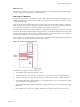
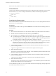
Table Of Contents
- Developing with VMware vCenter Orchestrator
- Contents
- Developing with VMware vCenter Orchestrator
- Developing Workflows
- Principal Phases in the Workflow Development Process
- Accessing the Orchestrator Client
- Testing Workflows During Development
- Workflow Editor
- Provide General Workflow Information
- Defining Attributes and Parameters
- Workflow Schema
- Obtaining Input Parameters from Users When a Workflow Starts
- Requesting User Interactions While a Workflow Runs
- Add a User Interaction to a Workflow
- Set the User Interaction security.group Attribute
- Set the timeout.date Attribute to an Absolute Date
- Calculate a Relative Timeout for User Interactions
- Set the timeout.date Attribute to a Relative Date
- Define the External Inputs for a User Interaction
- Define User Interaction Exception Behavior
- Create the Input Parameters Dialog Box for the User Interaction
- Respond to a Request for a User Interaction
- Calling Workflows Within Workflows
- Running a Workflow on a Selection of Objects
- Developing Long-Running Workflows
- Configuration Elements
- Workflow User Permissions
- Validating Workflows
- Running Workflows
- Develop a Simple Example Workflow
- Create the Simple Workflow Example
- Define the Simple Workflow Example Parameters
- Create the Simple Workflow Example Schema
- Link the Simple Workflow Example Elements
- Create Workflow Zones
- Define the Simple Workflow Example Decision Bindings
- Bind the Simple Workflow Example Action Elements
- Bind the Simple Workflow Example Scripted Task Elements
- Define the Simple Example Workflow Exception Bindings
- Set the Simple Workflow Example Attribute Read-Write Properties
- Set the Simple Workflow Example Parameter Properties
- Set the Layout of the Simple Workflow Example Input Parameters Dialog Box
- Validate and Run the Simple Workflow Example
- Develop a Complex Workflow
- Create the Complex Workflow
- Define the Complex Workflow Example Input Parameters
- Create a Custom Action For the Complex Workflow Example
- Create the Complex Workflow Example Schema
- Link the Complex Workflow Example Schema Elements
- Create the Complex Workflow Example Zones
- Define the Complex Workflow Example Bindings
- Set the Complex Workflow Example Attribute Properties
- Create the Layout of the Complex Workflow Example Input Parameters
- Validate and Run the Complex Workflow Example
- Scripting
- Orchestrator Elements that Require Scripting
- Limitations of the Mozilla Rhino Implementation in Orchestrator
- Using the Orchestrator API
- Access the Scripting Engine from the Workflow Editor
- Access the Scripting Engine from the Action or Policy Editor
- Access the Orchestrator API Explorer
- Use the Orchestrator API Explorer to Find Objects
- Writing Scripts
- Add Parameters to Scripts
- Accessing the Orchestrator Server File System from JavaScript and Workflows
- Accessing Java Classes from JavaScript
- Accessing Operating System Commands from JavaScript
- Exception Handling Guidelines
- Orchestrator JavaScript Examples
- Developing Actions
- Creating Resource Elements
- Creating Packages
- Index

Logical Flow of a Workflow
The logical flow of a workflow is the progression of the workflow from one element to the next in the schema
as the workflow runs. You define the logical flow of the workflow by linking elements in the schema.
The standard path is the path that the workflow takes through the logical flow if all elements run as expected.
The exception path is the path that the workflow takes through the logical flow if an element does not run as
expected.
Different styles of arrows in the workflow schema denote the different paths that the workflow can take
through its logical flow.
n
A black arrow denotes the standard path that the workflow takes from one element to the next.
n
A green arrow denotes the path that the workflow takes if a Boolean decision element returns true.
n
A red dotted arrow denotes the path that the workflow takes if a Boolean decision element returns
false.
n
A thick red dotted arrow denotes the exception path that the workflow takes if a workflow element does
not run correctly.
The following figure shows an example workflow schema that demonstrates the different paths that workflows
can take.
Figure 1-1. Different Workflow Paths Through the Logical Flow of the Workflow
This example workflow can take the following paths through its logical flow.
n
Standard path, true decision result, no exceptions.
a The decision element returns true.
b The SnapVMsInResourcePool workflow runs successfully.
c The sendHtmlEmail action runs successfully.
d The workflow ends successfully in the completed state.
n
Standard path, false decision result, no exceptions.
a The decision element returns false.
b The operation the scriptable task element defines runs successfully.
c The sendHtmlEmail action runs successfully.
d The workflow ends successfully in the completed state.
Chapter 1 Developing Workflows
VMware, Inc. 25