IMPLEMENTATION GUIDE EMC VSPEX END-USER COMPUTING VMware Horizon View 5.3 and VMware vSphere for up to 2,000 Virtual Desktops Enabled by EMC Next-Generation VNX and EMC Powered Backup EMC VSPEX Abstract This Implementation Guide describes the high-level steps required to deploy an EMC® VSPEX® End-User Computing solution for VMware Horizon View and VMware vSphere enabled by EMC next-generation VNX® storage and EMC Powered Backup.
Copyright © 2014 EMC Corporation. All rights reserved. Published in the USA. Published February 2014 EMC believes the information in this publication is accurate as of its publication date. The information is subject to change without notice. The information in this publication is provided as is.
Contents Contents Chapter 1 Introduction 7 Purpose of this guide.................................................................................................. 8 Business value ........................................................................................................... 8 Scope ......................................................................................................................... 9 Audience ...............................................................................
Contents Set up the initial VNX configuration ..................................................................... 29 Provision core data storage.................................................................................. 29 Provision storage for VMFS datastores (block only) .............................................. 29 Provision storage for NFS datastores (file only) .................................................... 30 Configure Fast Cache ....................................................
Contents Post-installation checklist ........................................................................................ 55 Deploy and test a single virtual desktop ................................................................... 55 Verify the redundancy of the solution components ................................................... 55 Chapter 6 Reference Documentation 57 EMC documentation .................................................................................................
Contents Tables 6 Table 1. Terminology......................................................................................... 10 Table 2. Tasks for pre-deployment .................................................................... 12 Table 3. Deployment workflow .......................................................................... 13 Table 4. Deployment prerequisites checklist ..................................................... 14 Table 1. Solution components ..........................
Chapter 1: Introduction Chapter 1 Introduction This chapter presents the following topics: Purpose of this guide ................................................................................................. 8 Business value ........................................................................................................... 8 Scope ......................................................................................................................... 9 Audience ................................
Chapter 1: Introduction Purpose of this guide The EMC® VSPEX® End-User Computing architecture provides the customer with a modern system capable of hosting a large number of virtual desktops at a consistent performance level. This VSPEX End-User Computing solution for VMware Horizon View 5.3 runs on a VMware vSphere virtualization layer backed by the highly available EMC VNX® family, which provides the storage. It is designed to be layered on a VSPEX Private Cloud for VMware vSphere Proven Infrastructure.
Chapter 1: Introduction Scope This Implementation Guide describes the high-level steps required to deploy the VSPEX End-User Computing solution for VMware Horizon View 5.3, which is layered on a VSPEX Private Cloud for VMware vSphere Proven Infrastructure . It provides examples of deployments on EMC next-generation VNX5200, VNX5400, and VNX5600 storage arrays. The same principles and guidelines apply to all next-generation VNX models that have been validated as part of the VSPEX program.
Chapter 1: Introduction Terminology Table 1 lists the terminology used in this guide. Table 1. Terminology Term Definition Linked clones Desktops provisioned as linked clones share a common base image within a desktop pool and therefore have a minimal storage footprint. Reference architecture The validated architecture that supports this VSPEX end-usercomputing solution at a particular point of scale—that is, 500, 1,000, or 2,000 virtual desktops.
Chapter 2: Before You Start Chapter 2 Before You Start This chapter presents the following topics: Overview .................................................................................................................. 12 Pre-deployment tasks .............................................................................................. 12 Deployment workflow .............................................................................................. 13 Essential reading ............................
Chapter 2: Before You Start Overview This chapter provides an overview of important information of which you need to be aware, documents with which you need to be familiar, and tasks you need to perform before you start implementing your VSPEX End-User Computing with VMware Horizon View solution. The Design Guide for this solution—EMC VSPEX End-User Computing: VMware Horizon View 5.
Chapter 2: Before You Start Deployment workflow To design and implement your end-user computing solution, refer to the process flow in Table 31. Table 3. Deployment workflow Step Action 1 Use the Customer Sizing Worksheet in the Design Guide to collect customer requirements. 2 Use the EMC VSPEX Sizing Tool to determine the recommended VSPEX reference architecture for your end-user computing solution, based on the user requirements collected in Step 1.
Chapter 2: Before You Start VSPEX Proven Infrastructure Guide Refer to the following VSPEX Proven Infrastructure Guide: EMC Powered Backup for VSPEX guide Refer to the following EMC Powered Backup for VSPEX guide: EMC VSPEX Private Cloud: VMware vSphere 5.
Chapter 2: Before You Start Requirement Description Software (file variant only) VMware Storage APIs for Array Integration (VAAI) Plug-in for VNX for File Licenses VMware vCenter 5.5 license key VMware vSphere Desktop license keys VMware Horizon View Premier 5.
Chapter 2: Before You Start 16 EMC VSPEX End-User Computing: VMware Horizon View 5.
Chapter 3: Solution Overview Chapter 3 Solution Overview This chapter presents the following topics: Overview .................................................................................................................. 18 VSPEX Proven Infrastructures................................................................................... 18 Solution architecture ............................................................................................... 19 Summary of key components ...................
Chapter 3: Solution Overview Overview This chapter provides an overview of the VSPEX End-User Computing for VMware Horizon View on VMware vSphere solution and the key technologies used in the solution. The solution has been designed and proven by EMC to provide the desktop virtualization, server, network, storage, and backup resources to support reference architectures at three points of scale: 500, 1000, and 2,000 virtual desktops.
Chapter 3: Solution Overview Figure 1. VSPEX Proven Infrastructures Solution architecture High-level architecture The EMC VSPEX End-User Computing for VMware Horizon View solution provides a complete system architecture capable of supporting up to 2,000 virtual desktops and validates the infrastructure at three points of scale—500, 1,000, and 2,000 virtual desktops. The solution supports two storage-type variants: block and file. EMC VSPEX End-User Computing: VMware Horizon View 5.
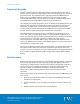
Chapter 3: Solution Overview Figure 2 shows the high-level architecture of the validated solution. Figure 2. Architecture of the validated solution The solution uses EMC VNX and VMware vSphere to provide the storage and virtualization platforms for a VMware Horizon View environment of Microsoft Windows 7 virtual desktops provisioned by VMware Horizon View Composer.
Chapter 3: Solution Overview virtual desktop performance. Users can adapt to slow performance, but unpredictable performance frustrates users and reduces efficiency. To provide predictable performance for end-user computing solutions, the storage system must be able to handle the peak I/O load from the clients while keeping response time to a minimum. However, deploying many disks to handle brief periods of extreme I/O pressure is expensive to implement.
Chapter 3: Solution Overview Summary of key components Table 1 summarizes the key technologies used in this solution. The Design Guide provides overviews of the individual components. Table 1. Solution components VSPEX layer Components Application layer VMware Horizon View 5.
Chapter 4: Solution Implementation Chapter 4 Solution Implementation This chapter presents the following topics: Overview .................................................................................................................. 24 Network implementation .......................................................................................... 25 Prepare and configure the storage array ..................................................................28 Install and configure the vSphere hosts ...
Chapter 4: Solution Implementation Overview This chapter describes how to implement the reference architectures of the end-user computing solution. If you already have a VSPEX Proven Infrastructure environment, you can skip the sections for the implementation steps already completed. Otherwise, refer to the VSPEX Proven Infrastructure Guide listed in Essential reading for information on configuring the required infrastructure components.
Chapter 4: Solution Implementation Network implementation This section describes the requirements for preparing the network infrastructure required to support this solution. Table 3 summarizes the tasks to be completed, with references for further information. Table 3. Configure the infrastructure network Tasks for switch and network configuration Task Description Reference Configure the infrastructure network Configure the storage array and vSphere host infrastructure networking.
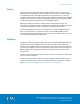
Chapter 4: Solution Implementation Figure 4 shows a sample redundant Ethernet infrastructure for this solution. It illustrates the use of redundant switches and links to ensure that no single point of failure exists in network connectivity. Figure 4. 26 Sample Ethernet network architecture EMC VSPEX End-User Computing: VMware Horizon View 5.
Chapter 4: Solution Implementation Configure the VLANs Configure the storage network (block variant) Ensure that there are adequate switch ports for the storage array and vSphere hosts.
Chapter 4: Solution Implementation Complete the network cabling Ensure that all solution servers, storage arrays, switch interconnects, and switch uplinks have redundant connections and are plugged into separate switching infrastructures. Ensure that there is a complete connection to the existing customer network. Note: At this point, the new equipment is connected to the existing customer network. Ensure that unforeseen interactions do not cause service issues on the customer network.
Chapter 4: Solution Implementation Prepare the VNX Set up the initial VNX configuration There are no specific setup steps for this solution.
Chapter 4: Solution Implementation 2. f. In the dialog box that appears, specify the pool parameters, and then click OK. g. Ensure that FAST Cache is enabled for the storage pool. Configure the required LUNs from the pool, as detailed in Table 6, to present to the vSphere servers as four VMFS datastores. Table 6. LUNs on VNX for storing virtual desktops Configuration Number of LUNs 500 virtual desktops 1,000 virtual desktops 2,000 virtual desktops 3.
Chapter 4: Solution Implementation 2. e. Click Create. f. In the dialog box that appears, specify the pool parameters, and then click OK. g. Ensure that FAST Cache is enabled for the pool. Configure the required LUNs from the pool, as detailed in Table 8, to present to the Data Mover as dvols of a system-defined NAS pool. Table 8. Configure LUNs for NAS pool Configuration .
Chapter 4: Solution Implementation Configuration Number of file systems 2,000 virtual desktops File system size (GB) 2 50 16 360 a. Select Storage > Storage Configuration > File Systems. b. In the dialog box that appears, click Create. c. Select Create from Storage Pool. d. In Storage Capacity, type the required number of file systems (as detailed in Table 9) and accept the default values for all other parameters. 4.
Chapter 4: Solution Implementation Configure Fast Cache To configure FAST Cache on the storage pool for this solution, complete the following steps in Unisphere: 1. To view FAST Cache information for the VNX array: a. In Unisphere, click Properties and select Manage Cache. b. In the Storage System Properties dialog box, shown in Figure 8, click FAST Cache to view FAST Cache information. Figure 8. 2. Storage System Properties dialog box To create FAST Cache: a.
Chapter 4: Solution Implementation Note: To determine the number of flash drives to use, refer to the Design Guide. c. With Automatic selected, flash drives that will be used for creating FAST Cache are listed in the bottom portion of the dialog box. To select the drives manually, select Manual. d. Click OK to create FAST Cache using the selected disks. Note: If a sufficient number of flash drives is not available, an error message appears and FAST Cache cannot be created. e.
Chapter 4: Solution Implementation Configuration Number of LUNs 2,000 virtual desktops . Configure FAST VP for user data 3. 10 LUN size (TB) 3 Provision four file systems from the NAS pool to be exported as CIFS shares on a CIFS server. You can configure FAST VP to automate data movement between storage tiers in the user data storage pool—this is optional. You can configure FAST VP at the pool level or at the LUN level.
Chapter 4: Solution Implementation Figure 11. Manage Auto-Tiering Window From this window, you can control the Data Relocation Rate. The default rate is set to Medium to avoid significantly affecting host I/O. Note: FAST VP is a completely automated tool and you can schedule relocations to occur automatically. EMC recommends that relocations be scheduled during off-peak hours to minimize any potential performance impact.
Chapter 4: Solution Implementation Provision optional storage for infrastructure virtual machines If the storage required for infrastructure virtual machines (that is, SQL Server, domain controller, vCenter Server, and Horizon View Connection servers) does not exist in the production environment already and you have purchased the optional user data disk pack, configure an NFS file system on the VNX to be used as the NFS datastore in which the infrastructure virtual machines reside.
Chapter 4: Solution Implementation Note: This alert is active only if there are thin LUNs in the pool, because thin LUNs provide the only way you can oversubscribe a pool. If the pool contains only thick LUNs, the alert is not active because there is no risk of running out of space due to oversubscription. You can also specify the value for Percent Full Threshold, which equals Total Allocation/Total Capacity, when a pool is created. Figure 14. 4.
Chapter 4: Solution Implementation Table 12 lists information about thresholds and their settings for VNX Operating Environment (OE) for Block Release 33. Table 12.
Chapter 4: Solution Implementation Install vSphere On initial power up of the servers being used for vSphere, confirm or enable the hardware-assisted CPU virtualization setting and the hardware-assisted MMU virtualization setting in the server’s BIOS. If the servers are equipped with a RAID controller, EMC recommends that you configure mirroring on the local disks. Start up the vSphere installation media and install the hypervisor on each of the servers.
Chapter 4: Solution Implementation 3. Select Properties. 4. Set the MTU size to 9,000. 5. Click OK to apply the changes. Jumbo frames might also need to be enabled on each network switch. Consult your switch configuration guide for instructions. Connect VMware datastores Connect the data stores configured in Prepare and configure the storage array to the appropriate vSphere servers.
Chapter 4: Solution Implementation Task Description Reference Configure the database for VMware vCenter Server Create the database required for vCenter Server on the appropriate datastore. Preparing vCenter Server Databases Configure the database for VMware Update Manager Create the database required for Update Manager on the appropriate datastore.
Chapter 4: Solution Implementation Task Description Reference Install the vCenter guest OS Install Windows Server 2008 R2 Standard Edition on the vCenter host virtual machine. VMware vSphere Documentation Update the virtual machine Install VMware Tools, enable hardware acceleration, and allow remote console access. vSphere Virtual Machine Administration Create vCenter ODBC connections Create the 64-bit vCenter and 32-bit vCenter Update Manager ODBC connections.
Chapter 4: Solution Implementation Task Description Reference Install EMC PowerPath Viewer (block variant) Install PowerPath Viewer on the administration console. EMC PowerPath Viewer Installation and Administration Guide Set up VMware View Connection Server This section provides information on how to set up and configure VMware View Connection Server for the solution. For a new installation of Horizon View, VMware recommends that you complete the tasks in the order shown in Table 16.
Chapter 4: Solution Implementation Install VMware View Connection Server Task Description Reference Connect VMware Horizon View to vCenter and View Composer Use the View Manager web interface to connect Horizon View to the vCenter server and View Composer. VMware Horizon View Administration Guide Prepare a master virtual machine Create a master virtual machine as the base image for the virtual desktops.
Chapter 4: Solution Implementation You can also enable Reclaim VM disk space. This feature is currently supported only with Windows 7 desktops. If you enable Reclaim VM disk space, you must specify a blackout period that controls when the operation should not process. As the operation should not execute during periods of heavy use, include those times in the blackout period. By default, space reclamation only runs when there is 1 GB of space or more to reclaim.
Chapter 4: Solution Implementation Configure View PCoIP group policies You control View PCoIP protocol settings using AD group policies that are applied to the OU containing the View Connection servers. The View group policy templates are located in the \Program Files\VMware\VMware View\Server\extras\GroupPolicyFiles directory on the View Connection server. Use the group policy template pcoip.
Chapter 4: Solution Implementation Figure 16. View Composer Disks window 8. Configure the AD group policy for View Persona Management. 9. Select Select separate datastores for replica and OS disk. 10. Select the appropriate parent virtual machine, virtual machine snapshot, folder, vSphere hosts or clusters, vSphere resource pool, and linked clone and replica disk datastores. 11. Enable host caching for the desktop pool and specify cache regeneration blackout times. 12.
Chapter 4: Solution Implementation Set up VMware vShield Endpoint This section provides information on how to set up and configure the components of vShield Endpoint. Table 17 describes the tasks to be completed. Note: EMC recommends that you put the OS volume for VMware vShield Endpoint into the VSPEX private cloud pool. Refer to the vShield Quick Start Guide for the recommended CPU and memory configuration. Table 17.
Chapter 4: Solution Implementation Verify desktop vShield Endpoint driver installation The vShield Endpoint driver is a subcomponent of the VMware Tools software package that is installed on the virtual desktop master image. The driver is installed using one of two methods: Select Complete during VMware Tools installation. Select Custom during VMware Tools installation. From the VMware Device Drivers list box, select VMCI Driver, and then select vShield Driver.
Chapter 4: Solution Implementation Set up VMware vCenter Operations Manager for Horizon View This section provides information on how to set up and configure VMware vCenter Operations Manager (vCOps) for Horizon View. Table 18 describes the tasks that must be completed. Note: EMC recommends that you put the OS volume for the VMware vCOps for Horizon View server into the VSPEX private cloud pool.
Chapter 4: Solution Implementation 52 Task Description Reference Install the vCOps for Horizon View Adapter software Deploy and configure the vCOps for Horizon View Adapter software. vCenter Operations Manager for View Integration Guide Import the vCOps for Horizon View PAK file Import the vCenter Operations Manager for Horizon View Adapter PAK file using the vCOps main web interface.
Chapter 5: Solution Verification Chapter 5 Solution Verification This chapter presents the following topics: Overview .................................................................................................................. 54 Post-installation checklist ....................................................................................... 55 Deploy and test a single virtual desktop ..................................................................
Chapter 5: Solution Verification Overview After you configure the solution, complete the tasks in Table 19 to verify the configuration and functionality of specific aspects of the solution and ensure that the configuration supports core availability requirements. Table 19. Tasks for testing the installation Task Description Reference Verify installation with post installation checklist Verify that adequate virtual ports exist on each vSphere host virtual switch.
Chapter 5: Solution Verification Post-installation checklist The following configuration items are critical to the functionality of the solution, and should be verified prior to deployment into production. On each vSphere server used as part of this solution, verify that: The vSwitches hosting the client VLANs are configured with sufficient ports to accommodate the maximum number of virtual machines a host can accommodate.
Chapter 5: Solution Verification b. 3. 56 To verify that network redundancy features function as expected, disable each of the redundant switching infrastructures in turn. While each of the switching infrastructures is disabled, verify that all the components of the solution maintain connectivity to each other and to any existing client infrastructure as well.
Chapter 6: Reference Documentation Chapter 6 Reference Documentation This chapter presents the following topics: EMC documentation .................................................................................................58 Other documentation ............................................................................................... 58 EMC VSPEX End-User Computing: VMware Horizon View 5.
Chapter 6: Reference Documentation EMC documentation The following documents, located on EMC Online Support provide additional and relevant information. Access to these documents depends on your login credentials. If you do not have access to a document, contact your EMC representative.
Chapter 6: Reference Documentation VMware Horizon View Security Guide VMware Horizon View Upgrades Guide VMware Horizon View 5.
Chapter 6: Reference Documentation 60 EMC VSPEX End-User Computing: VMware Horizon View 5.
Appendix A: Configuration Worksheet Appendix A Configuration Worksheet This appendix presents the following topic: Customer Configuration Worksheet .........................................................................62 EMC VSPEX End-User Computing: VMware Horizon View 5.
Appendix A: Configuration Worksheet Customer Configuration Worksheet Before configuring the solution, you need to gather some customer-specific configuration information such as IP addresses, hostnames, and so on. Table 20 to Table 25 provide a worksheet that you can use to record the information. You can also print and use the worksheet as a customer “leave behind” document for future reference. A standalone copy of the worksheet is attached to this document in Microsoft Office Word format.
Appendix A: Configuration Worksheet To confirm the customer information, cross-reference with the relevant array configuration worksheet: VNX Block Configuration Worksheet or VNX Installation Assistant for File/Unified Worksheet. Table 20.
Appendix A: Configuration Worksheet Table 23. Name Network infrastructure information Purpose IP Subnet mask Default gateway Ethernet switch 1 Ethernet switch 2 … Table 24. Name VLAN information Network purpose VLAN ID Allowed subnets Client access network Storage network Management network Table 25.