
Specifications
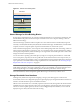
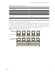
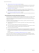

Table 4-11. Example of a VMware View Pod
Item Number
View building blocks 5
View Connection Servers 7 (1 for each building block and 2 spares)
10Gb Ethernet module 1
Modular networking switch 1
Load-balancing module 1
VPN for WAN 1 (optional)
The network core load balances incoming requests across View Connection Server instances. Support for a
redundancy and failover mechanism, usually at the network level, prevents the load balancer from becoming
a single point of failure. For example, the Virtual Router Redundancy Protocol (VRRP) communicates with the
load balancer to add redundancy and failover capability.
If a View Connection Server instance fails or becomes unresponsive during an active session, users do not lose
data. Desktop states are preserved in the virtual machine desktop so that users can connect to a different View
Connection Server instance and their desktop session resumes from where it was when the failure occurred.
Figure 4-2 shows how all the components can be integrated into one manageable entity.
Figure 4-2. Pod Diagram for 10,000 View Desktops
switched networks
VMware View
Connection Servers
VMware View
building blocks
load balancing
network core
Each switched network connects to each View Connection Server
Chapter 4 Architecture Design Elements and Planning Guidelines
VMware, Inc. 47