
7.0
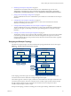

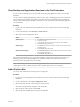
Table Of Contents
- Administering View Cloud Pod Architecture
- Contents
- Administering View Cloud Pod Architecture
- Introduction to Cloud Pod Architecture
- Designing a Cloud Pod Architecture Topology
- Creating Cloud Pod Architecture Sites
- Entitling Users and Groups in the Pod Federation
- Finding and Allocating Desktops and Applications in the Pod Federation
- Global Entitlement Example
- Cloud Pod Architecture Topology Limits
- Cloud Pod Architecture Port Requirements
- Security Considerations for Cloud Pod Architecture Topologies
- Setting Up a Cloud Pod Architecture Environment
- Initialize the Cloud Pod Architecture Feature
- Join a Pod to the Pod Federation
- Create and Configure a Global Entitlement
- Create and Configure a Site
- Assign a Home Site to a User or Group
- Create a Home Site Override
- Test a Cloud Pod Architecture Configuration
- Example: Setting Up a Basic Cloud Pod Architecture Configuration
- Managing a Cloud Pod Architecture Environment
- View a Cloud Pod Architecture Configuration
- View Pod Federation Health in View Administrator
- View Desktop and Application Sessions in the Pod Federation
- Add a Pod to a Site
- Modifying Global Entitlements
- Managing Home Site Assignments
- Remove a Pod From the Pod Federation
- Uninitialize the Cloud Pod Architecture Feature
- lmvutil Command Reference
- lmvutil Command Use
- Initializing the Cloud Pod Architecture Feature
- Disabling the Cloud Pod Architecture Feature
- Managing Pod Federations
- Managing Sites
- Managing Global Entitlements
- Managing Home Sites
- Viewing a Cloud Pod Architecture Configuration
- Listing Global Entitlements
- Listing the Pools in a Global Entitlement
- Listing the Users or Groups in a Global Entitlement
- Listing the Home Sites for a User or Group
- Listing the Effective Home Site for a User
- Listing Dedicated Desktop Pool Assignments
- Listing the Pods or Sites in a Cloud Pod Architecture Topology
- Managing SSL Certificates
- Index

2 Initializing the Example Configuration on page 24
To initialize the Cloud Pod Architecture feature, the View administrator logs in to the View
Administrator user interface for a View Connection Server instance in East Pod 1, selects View
Configuration > Cloud Pod Architecture, and clicks Initialize the Cloud Pod Architecture feature.
3 Joining Pods in the Example Configuration on page 24
The View administrator uses View Administrator to join Central Pod 1 and Central Pod 2 to the pod
federation.
4 Creating Sites in the Example Configuration on page 24
The View administrator uses View Administrator to create a site for the Eastern and Central
datacenters and adds pods to those sites.
5 Creating Global Desktop Entitlements in the Example Configuration on page 25
The View administrator uses View Administrator to create a single global desktop entitlement that
entitles all sales agents to all desktops in the sales agent desktop pools across all pods in the pod
federation.
6 Creating a View URL for the Example Configuration on page 25
The insurance company uses a single View URL and employs a DNS service to resolve sales.example
to the nearest pod in the nearest data center. With this arrangement, sales agents do not need to
remember different URLs for each pod and are always directed to the nearest data center, regardless
of where they are located.
Designing the Example Topology
The insurance company designs a Cloud Pod Architecture topology that includes a site for each region.
Figure 3‑1. Example Cloud Pod Architecture Topology
east1.example
East Pod 1
Eastern Region
east2.example east3.example
east4.example east5.example
central1.example
Central Pod 1
Central Region
central2.example central3.example
central4.example central5.example
central6.example
Central Pod 2
central7.example central8.example
central9.example central10.example
Sales A Sales B
Sales A
Sales B
Sales A
Sales B
In this topology, the Eastern region site contains a single pod, East Pod 1, that consists of five View
Connection Server instances called east1.example through east5.example.
The Central region site contains two pods, Central Pod 1 and Central Pod 2. Each pod contains five View
Connection Server instances. The View Connection Servers in the first pod are called central1.example
through central5.example. The View Connection Server instances in the second pod are called
central6.example through central10.example.
Each pod in the topology contains two desktop pools of sales agent desktops, called Sales A and Sales B.
Chapter 3 Setting Up a Cloud Pod Architecture Environment
VMware, Inc. 23