
Operating instructions


Installation Instructions K3 Series
7
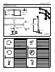
TOOLS REQUIRED FOR INSTALLATION
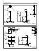
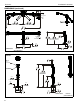
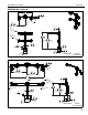
PARTS
#2
5/32” (included)
1/2” (for K3G mounts only)
3/16" (included)
5/16" (included)
Models
A B C D E F G H J K L M N P Q R S T U V W
K3F1203
1 2 1 1 1 4 6 8 8 8 8 8 0 0 1 1 1 0 0 0 0
K3F220
1 6 1 1 1 4 6 16 16 16 16 16 0 0 1 1 1 0 0 2 2
K3F310
1 3 1 1 1 4 6 12 12 12 12 12 0 0 1 1 1 0 0 0 0
K3G120
1 2 0 1 1 4 12 8 8 8 8 8 1 1 1 1 1 0 0 0 0
K3G220
1 6 0 1 1 4 12 16 16 16 16 16 1 1 1 1 1 0 0 2 2
K3G310
1 3 0 1 1 4 12 12 12 12 12 12 1 1 1 1 1 0 0 0 0
K3G320
1 6 0 1 1 4 6 24 24 24 24 24 1 1 1 1 1 4 4 2 2
QUANTITIES OF PARTS PER MODEL
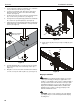
A
- Column/array assembly
(K3F310 shown as example)
B - Cable management covers (2 lengths)
[Quantities listed as total number of covers]
D - Column cap
E - Base cover
F - 1/4-20 x 1-1/4"
G - Bumper
H - M4 x 30mm
J - M4 x 20mm
K - M4 x 12mm
L - 3/8"
M - 3/4"
N - Grommet screw
and base
P - Grommet plate
Q - 5/16"
R - 3/16"
S - 5/32"
T - 3/8-16 x 2-3/4"
V - Array arm (left)
(K3G320 shown as example)
W - Array arm (right)
(K3G320 shown as example)
C - Table top base
U - 3/8"